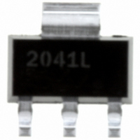
IPS2041LPBF International Rectifier, IPS2041LPBF Datasheet - Page 3

IPS2041LPBF
Manufacturer Part Number
IPS2041LPBF
Description
INTELLIGENT POWER SW 1CH SOT223
Manufacturer
International Rectifier
Type
Low Sider
Specifications of IPS2041LPBF
Input Type
Non-Inverting
Number Of Outputs
1
On-state Resistance
100 mOhm
Current - Output / Channel
1.4A
Current - Peak Output
5.5A
Voltage - Supply
4 V ~ 5.5 V
Operating Temperature
-40°C ~ 150°C
Mounting Type
Surface Mount
Package / Case
SOT-223 (3 leads + Tab), SC-73, TO-261
Current, Leakage, Offset
50 μA
Current, Supply
4 mA
Package Type
SOT-223
Polarization
N-Channel
Power Dissipation
1.6 W
Resistance, Drain To Source On
130 Milliohms
Temperature, Operating, Maximum
+150 °C
Temperature, Operating, Minimum
–40 °C
Time, Turn-off Delay
425 ns
Time, Turn-on Delay
675 ns
Voltage, Supply
39 V
Power Load Switch Type
Low Side
Input Voltage
5.5V
Current Limit
1.4A
On State Resistance
0.1ohm
Thermal Protection
Yes
On / Enable Input Polarity
Active Low
Power Dissipation Pd
1W
No. Of Outputs
1
Rohs Compliant
Yes
Lead Free Status / RoHS Status
Lead free / RoHS Compliant
Available stocks
Company
Part Number
Manufacturer
Quantity
Price
Company:
Part Number:
IPS2041LPBF
Manufacturer:
IR
Quantity:
12 500
Static Electrical Characteristics
Tj=25°C, Vcc=14V (unless otherwise specified)
Switching Electrical Characteristics
Vcc=14V, Resistive load=10Ω, Rinput=50Ω, Vin=5V, Tj=25°C
Protection Characteristics
(2) Guaranteed by design
www.irf.com
Symbol
Rds(on)
Idss1
Idss2
V clamp1
V clamp2
Vin clamp
Vth
Iin, on
Iin, off
Symbol
Tdon
Tr
Tdoff
Tf
Eon + Eoff
Symbol
Tsd
Isd
OV
Vreset
Treset
Over temperature threshold
Over current threshold
Over voltage protection ( not active when
the device is ON )
IN protection reset threshold
Time to reset protection
Parameter
ON state resistance Tj=25°C
ON state resistance Tj=150°C(2)
Drain to source leakage current
Drain to source leakage current
Drain to source clamp voltage 1
Drain to source clamp voltage 2
IN to source pin clamp voltage
Input threshold voltage
ON state IN positive current
OFF state IN positive current
( after protection latched )
Parameter
Turn-on delay time to 20%
Rise time 20% to 80%
Turn-off delay time to 80%
Fall time 80% to 20%
Turn on and off energy
Parameter
Min.
150(2)
Min.
Min.
15(2)
150
0.4
0.2
0.3
5.5
1.1
1.1
63
15
⎯
52
⎯
⎯
⎯
⎯
⎯
1
4
Typ.
Typ.
Typ.
0.01
0.04
165
100
180
250
1.3
0.9
1.3
5.5
1.6
6.2
12
55
50
68
68
40
3
2
Max.
Max.
Max.
500
130
240
350
7.5
2.7
75
80
⎯
⎯
⎯
⎯
4
2
8
3
7
2
1
2
IPS2041(L)(R)PbF
Units
Units
Units
mΩ
µA
µA
µs
µJ
°C
µs
V
A
V
V
Test Conditions
See figure 2
Vin=5V, Ids=1A
Vcc=50V, Tj=25°C
Id=20mA See fig. 3 & 4
Id=1A
Iin=1mA
Id=50mA
Vin=5V
Test Conditions
Vcc=14V, Tj=25°C
Test Conditions
See figure 1
See figure 1
Vin=0V, Tj=25°C
3


