IR3315PBF International Rectifier, IR3315PBF Datasheet
IR3315PBF
Specifications of IR3315PBF
Available stocks


Related parts for IR3315PBF


IR3315PBF Summary of contents
Page 1
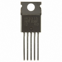
... IR3315 IN Ifb 10k Rifb Logic Power Ground Ground Data Sheet No. PD60285 IR3315(S)PbF Product Summary Rds(on) 20 mΩ max. Vcc op 32V Current Ratio Prog. Ishutdown Vclamp Packages TO-220 D²Pak IR3315PbF Pin 4 and 5 fused IR3315SPbF Vcc Battery Out Load 2800 3 to 30A 40V 1 ...
Page 2
Absolute Maximum Ratings Absolute maximum ratings indicate sustained limits beyond which damage to the device may occur. All voltage parameters are referenced to Vcc lead. (Tambient=25°C unless otherwise specified). Symbol Parameter Vcc-Vin Maximum Vcc voltage Vcc-Vin cont. Maximum continuous Vcc ...
Page 3
Protection Characteristics Tj=25°C, Rifb=500 to 5kΩ Symbol Parameter Vifb-Vin@Isd Over-current s hutdown threshold Tsd Over temperature threshold OV Over voltage protection (not latched) Isdf Fixed over current shutdown Isd_1k Programmable over current shutdown 1k Treset Time to reset protection Min. ...
Page 4
Current Sense Characteristics Symbol Parame ter Ratio I Load/Iifb current ratio Ratio_TC I Load/Iifb variation aver temp Offset Load current diagnostic offset Trst Ifb response time (low signal) Functional Block Diagram All values are typ ical 43V 3mA + - ...
Page 5
Lead Assignments TO220 Vcc-Vin Vih Vil Vhyst Vcc IN IR3315 Iin Ifb Out Ifb Figure 1 – Voltages and current definitions www.irf.com Ifb Out ...
Page 6
T clamp Vin Iout Vcc Vout Vcc - V clamp See Application Notes to evaluate power dissipation Figure 3 – Active clamp waveforms Vcc-Vin Over-current shutdown Iout Tj www.irf.com Vcc-Vin t < T reset t > T reset Wait Over-temperature ...
Page 7
A ll curves are typical characteristics. Operation in hatched areas is not recommended. Tj=25°C, Rifb=500ohm, Vcc=14V (u nless otherwise specified Vcc-Vin, supply voltage (V) Figure 6 – Icc (mA) ...
Page 8
With calibration Spec. Max load, load current (A) F igure 10 – Error (+/- load ( - mb., ambient temperature (°C Figure 12 ...
Page 9
Pr otection response time (s Figure 14 – Ids (A) Vs over temperature prote response time (s) www.irf.com Tamb=25°C Tamb=100°C 1.E+01 1.E+02 1.E+03 ) ction IR3315(S)PbF 100 50°C/W free air 10 5°C/W 1 0.1 0.01 ...
Page 10
Case Outline – TO220 5 leads - Automotive Q100 PbF qualified www.irf.com IR3315(S)PbF 10 ...
Page 11
Case Outline 5 Lead - D2PAK - Automotive Q100 PbF MSL1 qualified www.irf.com IR3315(S)PbF 11 ...
Page 12
Tape & Reel 5 Lead - D2PAK IR WORLD HEADQUARTERS: 233 Kansas St., El Segundo, California 90245 Tel: (310) 252-7105 www.irf.com This product has been designed and qualified for the Automotive [Q100] market. Qualification standards can be found at www.irf.com ...
Page 13
Note: For the most current drawings please refer to the IR website at: http://www.irf.com/package/ ...