MAX256ASA+ Maxim Integrated Products, MAX256ASA+ Datasheet - Page 11

MAX256ASA+
Manufacturer Part Number
MAX256ASA+
Description
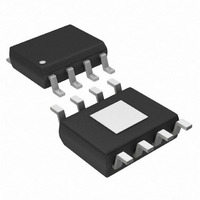
IC DVR H-BRIDGE 3W 8-SOIC
Manufacturer
Maxim Integrated Products
Type
H Bridger
Datasheet
1.MAX256ASA.pdf
(14 pages)
Specifications of MAX256ASA+
Input Type
Non-Inverting
Number Of Outputs
2
On-state Resistance
500 mOhm
Current - Output / Channel
600mA
Current - Peak Output
1A
Voltage - Supply
3 V ~ 5.5 V
Operating Temperature
-40°C ~ 125°C
Mounting Type
Surface Mount
Package / Case
8-SOIC (3.9mm Width) Exposed Pad, 8-eSOIC. 8-HSOIC
Supply Voltage (max)
5.5 V
Supply Voltage (min)
3 V
Maximum Operating Temperature
+ 125 C
Mounting Style
SMD/SMT
Maximum Power Dissipation
1509 mW
Minimum Operating Temperature
- 40 C
Supply Current
1.06 mA
Supply Voltage
5V
Digital Ic Case Style
SOIC
No. Of Pins
8
No. Of Regulated Outputs
2
Operating Temperature Range
-40°C To +125°C
Device Type
Half Bridge
Filter Terminals
SMD
Rohs Compliant
Yes
Lead Free Status / RoHS Status
Lead free / RoHS Compliant
Figure 6. Isolated Power Supply for Process Control Applications
As with all power-supply designs, it is important to opti-
mize efficiency. In designs incorporating small trans-
formers, the possibility of thermal runaway makes low
transformer efficiencies problematic. Transformer loss-
es produce a temperature rise that reduces the effi-
ciency of the transformer. The lower efficiency, in turn,
produces an even larger temperature rise.
To ensure that the transformer meets these require-
ments under all operating conditions, the design should
focus on the worst-case conditions. The most stringent
demands on ET product arise for minimum switching
frequency, maximum input voltage, maximum tempera-
ture, and load current. Additionally, the worst-case val-
ues for transformer and rectifier losses should be
considered.
The primary should be a single winding; however, the
secondary can be center-tapped, depending on the
desired rectifier topology. In most applications, the
phasing between primary and secondary windings is
not significant. Half-wave rectification architectures are
possible with the MAX256; however, these are discour-
aged. If a net DC current results due to an imbalanced
3W Primary-Side Transformer H-Bridge Driver
RS485
______________________________________________________________________________________
OPTOISOLATORS
MPU
V
CC
load, the magnetic flux in the core is increased. This
reduces the effective ET product and can lead to satu-
ration of the transformer core.
Transformers for use with the MAX256 are typically
wound on a high-permeability magnetic core. To mini-
mize radiated electromagnetic emissions, select a
toroid, pot core, E/I/U core, or equivalent.
The MAX256 can be operated from a +3.3V supply by
increasing the turns ratio of the transformer, or by
designing a voltage-doubler or voltage-tripler circuit as
shown in Figure 1B.
Optimum performance at +3.3V is obtained with fewer
turns on the primary winding, since the ET product
is lower than for a +5V supply. However, any of the
transformers for use with a +5V supply will operate
properly with a +3.3V supply. For a given power level,
the transformer currents are higher with a +3.3V supply
than with a +5V supply. Therefore, the DC resistance
of the transformer windings has a larger impact on the
circuit efficiency.
MAX256
V
CC
for Isolated Supplies
OPTOISOLATORS
M
U
X
DAC/ADC
+3.3V Operation
+15V
COMMON
-15V
11


