T6819-TBS Atmel, T6819-TBS Datasheet - Page 5
T6819-TBS
Manufacturer Part Number
T6819-TBS
Description
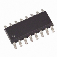
IC DRIVER DUAL TRPL DMOS 16-SOIC
Manufacturer
Atmel
Type
High Side/Low Side Driverr
Datasheet
1.T6819-TBQ.pdf
(16 pages)
Specifications of T6819-TBS
Input Type
Serial
Number Of Outputs
6
On-state Resistance
500 mOhm
Current - Output / Channel
1.5A
Current - Peak Output
2A
Voltage - Supply
7 V ~ 40 V
Operating Temperature
-40°C ~ 150°C
Mounting Type
Surface Mount
Package / Case
16-SOIC (3.9mm Width)
For Use With
ATAB6819 - BOARD EVAL FOR T6819/ATA6829
Lead Free Status / RoHS Status
Contains lead / RoHS non-compliant


After power-on reset, the input register has the following status:
The following patterns are used to enable internal test modes of the IC. It is not recommended to use these patterns during
normal operation.
4531D–BCD–07/04
Bit 15
Bit 15
SI
H
H
H
H
Bit 14
Bit 14
OCS
H
H
H
H
Bit 13
(OCS)
Bit 13
OLD
H
H
H
H
Bit 12
Bit 12
PH3
H
L
L
L
Bit 11
Bit 11
PL3
H
L
L
Table 2. Output Data Protocol
L
Bit
10
11
12
13
14
15
0
1
2
3
4
5
6
7
8
9
Bit 10
Bit 10
PH2
H
L
L
L
Output (Status)
Status HS1
Status HS2
Status HS3
Status LS1
Status LS2
Status LS3
Register
Bit 9
Bit 9
PL2
H
n. u.
n. u.
n. u.
n. u.
n. u.
n. u.
OVL
PSF
L
L
INH
L
TP
Bit 8
Bit 8
PH1
H
L
L
L
Function
Temperature prewarning: high = warning
Normal operation: high = output is on, low = output is off
Open-load detection: high = open load, low = no open load
(correct load condition is detected if the corresponding output is
switched off); not affected by SRR
Normal operation: high = output is on, low = output is off
Open-load detection: high = open load, low = no open load
(correct load condition is detected if the corresponding output is
switched off); not affected by SRR
Description see LS1
Description see HS1
Description see LS1
Description see HS1
Not used
Not used
Not used
Not used
Not used
Not used
Over-load detected: set high, when at least one output is switched
off by a short-circuit condition or an overtemperature event. Bits 1
to 6 can be used to detect the affected switch.
(open-load detection bit OLD = high)
Inhibit: this bit is controlled by software (bit SI in input register)
High = standby, low = normal operation
Power-supply fail: undervoltage at pin VS detected
Bit 7
Bit 7
PL1
H
L
L
L
(HS3)
Bit 6
Bit 6
T6819/T6829 [Preliminary]
HS3
L
L
L
L
(LS3)
Bit 5
Bit 5
LS3
L
L
L
L
(HS2)
Bit 4
Bit 4
HS2
L
L
L
L
(LS2)
Bit 3
Bit 3
LS2
L
L
L
L
(HS1)
Bit 2
Bit 2
HS1
L
L
L
L
(LS1)
Bit 1
Bit 1
LS1
L
L
L
L
(SRR)
Bit 0
Bit 0
SRR
L
L
L
L
5
Related parts for T6819-TBS
Image
Part Number
Description
Manufacturer
Datasheet
Request
R

Part Number:
Description:
IC DRIVER DUAL TRPL DMOS 16-SOIC
Manufacturer:
Atmel
Datasheet:

Part Number:
Description:
(T6819 / T6829) Dual Triple DMOS Output Driver
Manufacturer:
ATMEL Corporation
Datasheet:

Part Number:
Description:
MOSFET & Power Driver ICs Dual Triple Driver w/PWM Ctrl.
Manufacturer:
Atmel
Part Number:
Description:
MOSFET & Power Driver ICs Dual Triple Driver w/PWM Ctrl.
Manufacturer:
Atmel
Datasheet:

Part Number:
Description:
DEV KIT FOR AVR/AVR32
Manufacturer:
Atmel
Datasheet:
Part Number:
Description:
INTERVAL AND WIPE/WASH WIPER CONTROL IC WITH DELAY
Manufacturer:
ATMEL Corporation
Datasheet:
Part Number:
Description:
Low-Voltage Voice-Switched IC for Hands-Free Operation
Manufacturer:
ATMEL Corporation
Datasheet:
Part Number:
Description:
MONOLITHIC INTEGRATED FEATUREPHONE CIRCUIT
Manufacturer:
ATMEL Corporation
Datasheet:
Part Number:
Description:
AM-FM Receiver IC U4255BM-M
Manufacturer:
ATMEL Corporation
Datasheet:
Part Number:
Description:
Monolithic Integrated Feature Phone Circuit
Manufacturer:
ATMEL Corporation
Datasheet:
Part Number:
Description:
Multistandard Video-IF and Quasi Parallel Sound Processing
Manufacturer:
ATMEL Corporation
Datasheet:
Part Number:
Description:
High-performance EE PLD
Manufacturer:
ATMEL Corporation
Datasheet: