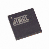
ATA6830-PKH Atmel, ATA6830-PKH Datasheet - Page 8

ATA6830-PKH
Manufacturer Part Number
ATA6830-PKH
Description
IC DRIVER MOTOR STEPPER 28-QFN
Manufacturer
Atmel
Datasheet
1.ATA6830-PKH.pdf
(23 pages)
Specifications of ATA6830-PKH
Applications
Stepper Motor Driver
Number Of Outputs
1
Current - Output
1.1A
Voltage - Supply
7 V ~ 20 V
Operating Temperature
-40°C ~ 105°C
Mounting Type
Surface Mount
Lead Free Status / RoHS Status
Contains lead / RoHS non-compliant
Package / Case
-
Voltage - Load
-
Other names
ATA6830-PKHTR
Bus Commands
Table 1. Bus Commands
8
Bus Command
Synchronization
Reference run (extend)
Reference run (retract)
New position (0 = full extension)
New position (0 = full retraction)
New position
(testmode, 0 = full extension)
New position
(testmode, 0 = full retraction)
ATA6830
D8
D8
D8
D8
7
1
0
0
There are different commands for controlling the stepping motor. Table 1 shows a list of
all implemented commands and their meanings. The first command, the synchronization
sequence, is described above. The second group of commands are the reference com-
mands. A reference run command causes the stepping motor to make an initial run. It is
used to establish a defined start position for the following position commands. The way
the reference run is executed will be described later. There are two reference run com-
mands. The difference is the turn direction of the stepping motor. This makes the circuit
more flexible for different applications. The turn direction is coded in the 4 identifier bits.
The last class of commands are the position commands. Every new position will be sent
as an absolute value. This makes the transmission more safe in terms of losing a posi-
tion command. The next received command tells the stepping motor the right position
again. For the position data there are 10 bits available (D0 to D9).
The maximum possible step count to be coded with 10 bit is 1024. Though position com-
mands up to 1024 will be executed, it´s prohibited to use values higher than 698, as this
is the step count of the reference run. For details see chapter “Reference Run”.
There are 4 new position commands. They differ in the identifier and in the modus bits.
The identifier fixes the turn direction. For test purposes there are new position com-
mands with a different mode. In this mode the stepping motor works with a reduced coil
current. This may be used for end tests in the production of the application.
Any command with modus or identifier different to the first reference run will be ignored.
Thus it is also not possible to change modus or identifier by performing a second refer-
ence run.
Data
D9
D9
D9
D9
6
0
0
0
5
1
0
0
0
0
1
1
Mode
High Byte
4
0
0
0
0
0
1
1
3
1
1
0
1
0
1
0
Identifier
2
0
0
1
0
1
0
1
1
1
0
1
0
1
0
1
0
0
1
0
1
0
1
0
D0
D0
D0
D0
7
1
0
0
D1
D1
D1
D1
6
0
0
0
D2
D2
D2
D2
5
1
0
0
Low Byte
D3
D3
D3
D3
4
0
0
0
Data
D4
D4
D4
D4
3
1
0
0
D5
D5
D5
D5
2
0
0
0
4575C–BCD–05/03
D6
D6
D6
D6
1
1
0
0
D7
D7
D7
D7
0
0
0
0


