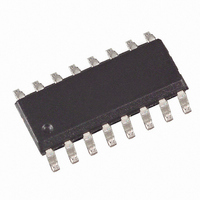
U2010B-MFPG3Y Atmel, U2010B-MFPG3Y Datasheet - Page 5

U2010B-MFPG3Y
Manufacturer Part Number
U2010B-MFPG3Y
Description
IC PHASE-CTRL W/CURR FDBK 16SOIC
Manufacturer
Atmel
Type
Phase Control ICr
Specifications of U2010B-MFPG3Y
Applications
AC Motor Controller
Number Of Outputs
1
Voltage - Supply
14.5 V ~ 16.5 V
Operating Temperature
-10°C ~ 100°C
Mounting Type
Surface Mount
Package / Case
16-SOIC (3.9mm Width)
Mounting Style
SMD/SMT
Operating Temperature (min)
-10C
Operating Temperature Classification
Commercial
Package Type
SOIC
Rad Hardened
No
Lead Free Status / RoHS Status
Lead free / RoHS Compliant
Current - Output
-
Voltage - Load
-
Lead Free Status / Rohs Status
Lead free / RoHS Compliant
2.6
2.7
4712D–AUTO–03/11
Voltage Synchronization with Mains Voltage Compensation, Pin 7
Load Current Detection, Pin 1
The voltage detector synchronizes the reference ramp with the mains supply voltage. At the
same time, the mains-dependent input current at pin 7 is shaped and rectified internally. This
current activates automatic retriggering and at the same time is available at pin 3
page
Automatic retriggering and mains voltage compensation are not activated until
increases to 8V. The resistance R
synchronization current, and hence the mains supply voltage compensation current. If the mains
voltage compensation and the automatic retriggering are not required, both functions can be
suppressed by limiting
Figure 2-2.
A further feature of the IC is the selection between soft start and load-current compensation.
Soft start is possible by connecting a capacitor between pin 1 and pin 4
In the case of load-current compensation, pin 1 is directly connected with resistance R
used for sensing load current.
The circuit continuously measures the load current as a voltage drop at resistor R
tion and use of both half waves results in a quick reaction to load-current change. Due to voltage
at resistor R
internal current source, whose positive current values are available at pin 3 (see
page
detection and the mains-voltage compensation (see
The effective control voltage is the final current at pin 3 together with the desired value network.
An increase of mains voltage causes an increase of the control angle . An increase of load
current results in a decrease of the control angle. This avoids a decrease in revolution by
increasing the load as well as an increase of revolution by the increment of mains supply
voltage.
9). The output current generated at pin 3 contains the difference from the load-current
9). By suitable dimensioning, it is possible to attain the specified compensation effect.
6
, there is an increase of input current at pin 1. This current increase controls the
Suppression of Automatic Retriggering and Mains Voltage Compensation
V
7
– V
4
BZX55
C6V2
Mains
2x
sync.
R
2
7 V (see
defines the width of the zero voltage cross-over pulse,
Figure
Figure 5-5 on page
7
4
2-2).
Atmel
U2008B
Atmel U2008B
9).
(Figure 5-4 on page
(Figure 5-5 on
6
Figure 5-7 on
. The evalua-
6
V
, which is
7
- V
4
8).
5


