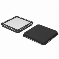
AMIS30623C623BRG ON Semiconductor, AMIS30623C623BRG Datasheet - Page 36

AMIS30623C623BRG
Manufacturer Part Number
AMIS30623C623BRG
Description
IC MOTOR DRIVER/CTLR 32-QFP
Manufacturer
ON Semiconductor
Datasheet
1.AMIS30623C6239RG.pdf
(61 pages)
Specifications of AMIS30623C623BRG
Applications
Stepper Motor Driver
Number Of Outputs
1
Current - Output
800mA
Voltage - Supply
6.5 V ~ 29 V
Operating Temperature
-40°C ~ 165°C
Mounting Type
Surface Mount
Package / Case
32-VSQFP
Mounting Style
SMD/SMT
Lead Free Status / RoHS Status
Lead free / RoHS Compliant
Voltage - Load
-
Lead Free Status / Rohs Status
Lead free / RoHS Compliant
Available stocks
Company
Part Number
Manufacturer
Quantity
Price
Company:
Part Number:
AMIS30623C623BRG
Manufacturer:
ON Semiconductor
Quantity:
1 850
Company:
Part Number:
AMIS30623C623BRG
Manufacturer:
ON Semiconductor
Quantity:
10 000
General Description
communications protocol that efficiently supports the
control of mechatronics nodes in distributed automotive
applications. The physical interface implemented in the
AMIS−30623 is compliant to the LIN rev. 2.0 & 2.1
specifications. It features a slave node, thus allowing for:
•
•
•
•
•
Slave Operational Range for Proper Self
Synchronization
following conditions:
•
•
battery voltage protection diode for the Master and the Slave
nodes.
Functional Description
Analog Part
and slope control. The receiver mainly consists of a
comparator with a threshold equal to V
Table 30. LIN ERROR REGISTER
The LIN (local interconnect network) is a serial
The LIN interface will synchronize properly in the
It is highly recommended to use the same type of reverse
The transmitter is a low−side driver with a pull−up resistor
single−master / multiple−slave communication
self synchronization without quartz or ceramics
resonator in the slave nodes
guaranteed latency times for signal transmission
single−signal−wire communication
transmission speed of 19.2 kbit/s
Vbat ≥ 8 V
Ground shift between master node and slave node < ±1 V
Bit 7
used
Not
Bit 6
used
Not
Bit 5
used
Not
control
block
BB
to
/2. Figure 5 shows
LIN address
from OTP
Figure 21. LIN Interface
LIN CONTROLLER
Bit 4
used
http://onsemi.com
protocol
Not
handler
LIN
36
RxD
TxD
•
•
•
•
protocol handler.
pull−up resistor as a transmitter, and a resistive divider with
a comparator as a receiver. The specification of the line
driver/receiver follows the ISO 9141 standard with some
enhancements regarding the EMI behavior.
the characteristics of the transmitted and received signal.
See AC Parameters for timing values.
Protocol Handler
This block implements:
•
•
•
•
•
Error Status Register
error status of the LIN communication. This register is as
follows:
out error
It includes the analog physical layer and the digital
The analog circuitry implements a low side driver with a
The LIN interface implements a register containing an
Time
selectable length of Message Frame: 2, 4, and 8 bytes
configuration flexibility
data checksum (classic checksum, cf. LIN1.3) security
and error detection
detection of defective nodes in the network
Bit synchronization
Bit timing
The MAC layer
The LLC layer
The supervisor
Bit 3
Control
Slope
Filter
V
BB
30 kW
error Flag
Bit 2
Data
LIN
HW0
HW1
HW2
error Flag
Header
Bit 1
error Flag
Bit 0
Bit


