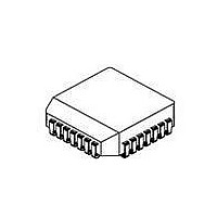
NJM3773FM2 NJR, NJM3773FM2 Datasheet

NJM3773FM2
Specifications of NJM3773FM2
Available stocks
Related parts for NJM3773FM2
NJM3773FM2 Summary of contents
Page 1
... Digital filter on chip eliminates external filtering components • Packages DIP22 / PLCC28 / EMP24(Batwing) BLOCK DIAGRAM NJM3773 Figure 1. Block diagram DUAL STEPPER MOTOR DRIVER Phase Dis – – – Dis Phase V C GND NJM3773 PACKAGE OUTLINE NJM3773E3 NJM3773D2 NJM3773FM2 Logic MM1 V MM2 M B2 Logic ...
Page 2
... Phase Phase Dis Dis when Phase is HIGH when Phase is HIGH NJM3773 NJM3773FM2 GND when Phase is HIGH ground when Phase is HIGH and V should be connected together. MM1 MM2 and M . Motor current flows from and a 4 700 pF capacitor to ground CC and M . Motor current flows from M ...
Page 3
FUNCTIONAL DESCRIPTION Each channel of the NJM3773 consists of the following sections: an output H-bridge with four transistors and four recirculation diodes, capable of driving up to 750 mA continuous current to the motor winding, a logic section that controls ...
Page 4
ABSOLUTE MAXIMUM RATINGS Parameter Voltage Logic supply Motor supply Logic inputs Analog inputs Current Motor output current Logic inputs Analog inputs Temperature Operating junction temperature Storage temperature Power Dissipation (Package Data) Power dissipation +25 C, DIP and ...
Page 5
ELECTRICAL CHARACTERISTICS Electrical characteristics over recommended operating conditions, unless otherwise noted. -20 C Parameter General Supply current Supply current Total power dissipation Total power dissipation Thermal shutdown junction temperature Turn-off delay Logic Inputs Logic HIGH input voltage Logic LOW input ...
Page 6
APPLICATIONS INFORMATION Current control The regulated output current level to the motor winding is determined by the voltage at the reference input and the value of the sensing resistor expressed as [A] M,peak ...
Page 7
Current sense filtering At turn-on a current spike occurs, due to the recovery of the recirculation diodes and the capacitance of the motor winding. To prevent this spike from reseting the flip-flops through the current sensing comparators, the clock oscillator ...
Page 8
V (Reference) inputs R The comparator inputs of NJM3773 (V gives a great deal of flexibility in selecting a suitable voltage divider network to interface to different types of Digital- to-Analog converters. Unbuffered DACs are preferably interfaced by a high ...
Page 9
Half-step mode. In the half-step mode, the current in one winding is brought to zero before a complete current reversal is made. The motor will then have taken two half steps equalling one full step in rotary movement. The cycle ...


