NJM3774D2 NJR, NJM3774D2 Datasheet
NJM3774D2
Specifications of NJM3774D2
Available stocks


Related parts for NJM3774D2


NJM3774D2 Summary of contents
Page 1
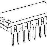
... Specially matched to the Dual DAC NJU39610 • Packages DIP22 / PLCC28 BLOCK DIAGRAM NJM3774 Figure 1. Block diagram DUAL STEPPER MOTOR DRIVER Phase Dis – – – Dis Phase V C GND NJM3774 PACKAGE OUTLINE NJM3774D2 NJM3774FM2 Logic MM1 V MM2 M B2 Logic ...
Page 2
PIN CONFIGURATIONS V 5 MM2 NJM3774FM2 GND MM1 Figure 2. Pin configurations PIN DESCRIPTION PLCC DIP Symbol Description 1- GND Ground and ...
Page 3
FUNCTIONAL DESCRIPTION Each channel of the NJM3774 consists of the following sections: an output H-bridge with four transistors, capable of driving up to 1000mA continuous current to the motor winding; a logic section that controls the output transistors; an S-R ...
Page 4
ABSOLUTE MAXIMUM RATINGS Parameter Voltage Logic supply Motor supply Logic inputs Comparator inputs Reference inputs Current Motor output current Logic inputs Analog inputs Temperature Operating Junction temperature Storage temperature Power Dissipation (Package Data) Power dissipation +25 C, ...
Page 5
ELECTRICAL CHARACTERISTICS Electrical characteristics over recommended operating conditions unless otherwise noted Parameter General Supply current Total power dissipation Total power dissipation Thermal shutdown junction temperature Turn-off delay Logic Inputs Logic HIGH input voltage Logic LOW input voltage ...
Page 6
APPLICATIONS INFORMATION Current control The output current to the motor is de-termined by the voltage at the reference input and value of sensing resistor Chopping frequency, winding induc-tance and supply voltage also affect the current, but to ...
Page 7
The frequency of the clock oscillator is set by the R values result in a clock frequency (= switching frequency) of 26.5 kHz. A lower frequency will result in higher current ripple, but may improve low-current level linearity. A higher ...
Page 8
Programming Figure 8 shows the different input and output sequences for full-step, half-step and modified halfstep operations. Full-step mode Both windings are energized at all the time with the same current, I current direction (and the magnetic field direction) in ...
Page 9
TYPICAL CHARACTERISTICS P (W) D 3.0 2.0 1 0.20 0.40 0.60 0.80 I (A) M Figure 10. Power dissipation vs. motor current ( 1.2 1.0 0.8 0.6 0.4 0 ...