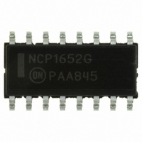
NCP1652DR2G ON Semiconductor, NCP1652DR2G Datasheet - Page 22

NCP1652DR2G
Manufacturer Part Number
NCP1652DR2G
Description
IC PFC CONTROLLER CCM/DCM 16SOIC
Manufacturer
ON Semiconductor
Datasheet
1.NCP1652DR2G.pdf
(34 pages)
Specifications of NCP1652DR2G
Mode
Continuous Conduction (CCM), Discontinuous Conduction (DCM)
Frequency - Switching
100kHz
Current - Startup
5.62mA
Voltage - Supply
9.3 V ~ 20 V
Operating Temperature
-40°C ~ 125°C
Mounting Type
Surface Mount
Package / Case
16-SOIC (3.9mm Width)
Switching Frequency
20 KHz to 250 KHz
Maximum Operating Temperature
+ 125 C
Mounting Style
SMD/SMT
Minimum Operating Temperature
- 40 C
Lead Free Status / RoHS Status
Lead free / RoHS Compliant
Other names
NCP1652DR2GOSTR
to prevent the controller from dissipating excessive power
if the V
current source (I
to achieve accurate PFC. Filtering the rectified ac line
voltage with a large bulk capacitor distorts the PFC in a
single stage PFC converter. A peak charger is needed to bias
An internal supervisory circuit monitors the V
The rectified ac line voltage is provided to the power stage
Figure 58. V
CC
pin is accidentally grounded. A lower level
inhibit
CC
) charges C
Double Hiccup Operation with a Fault Occurring while the Startup Circuit is Disabled
CC
Figure 59. Startup Current at Various V
Fault Timer
from 0 V to V
(internal)
V
V
OUTA
CC(on)
CC(off)
V
CC
Overload
CC
applied
voltage
t
http://onsemi.com
OVLD
inhibit
,
22
typically 0.85 V. Once V
current source is enabled. This behavior is illustrated in
Figure 59. This slightly increases the total time to charge
V
the HV pin as shown in Figure 60. Otherwise, the HV pin
follows the ac line and the startup circuit is disabled every
time the ac line voltage approaches 0 V. The V
is sized to bias the controller during power up.
CC
, but it is generally not noticeable.
CC
Levels
t
t
t
CC
exceeds V
inhibit
, the startup
CC
capacitor


