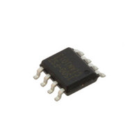
CS1500-FSZ Cirrus Logic Inc, CS1500-FSZ Datasheet

CS1500-FSZ
Specifications of CS1500-FSZ
Available stocks
Related parts for CS1500-FSZ
CS1500-FSZ Summary of contents
Page 1
... The digital controller optimizes the system stability and transient performance, simplifies the PFC design, reduces the external component count and BOM costs. The simple design and minimum cost makes CS1500 the ideal choice for PFC up to 300 watts. Ordering Information See ...
Page 2
... Regulator POR + - ADC ADC Figure 1. CS1500 Block Diagram system stability and transient response. No external feedback error signal compensation components are required. The CS1500s digital controller algorithm limits the ON time of the Power MOSFET by the following equation rect Where and V on rect sudden line surge or sporadic, high dv/dt line voltages, this equation may not limit the ON time appropriately ...
Page 3
... IFB GND 8-lead S OIC Figure 2. CS1500 Pin Assignments Table 1. Pin Descriptions NC — No connections Rectifier Voltage Sense — A current proportional to the rectified line voltage (V fed into this pin. The current is measured with an A/D converter. Link Voltage Sense — A current proportional to the output link voltage (V PFC is fed into this pin. The current is measured with an A/D converter. Ground — ...
Page 4
... 100mA,V = 13V -200mA,V = 13V =1nF,V = 13V =1nF,V = 13V -200mA,V = 13V 100mA,V = 13V O(startup) V O(nom OVP(Hy 360 5.2 Start-up vs. Normal Operation Mode CS1500 = GND = Min Typ Max 8.4 8.8 9.3 DD(on) 7.1 7.4 7.9 DD(off) - 1.4 - Hys V 17.0 17.9 18 1.7 1 ...
Page 5
... Operation at or beyond these limits may result in permanent damage to the device. Normal operation is not guaranteed at these extremes. DS849F1 CONFIDENTIAL Parameter =50° Human Body Model Machine Model Charged Device Model WARNING: CS1500 Value Unit -0 -0 ...
Page 6
... DD Figure 3. Supply Current vs. Supply Voltage 2 1.5 1 0 TEMP ( o C) Figure 5. UVLO Hysteresis vs. Temp 6 CONFIDENTIAL -50 Figure 4. Start-up & UVLO vs. Temp 19 18.5 18 17.5 17 100 150 -50 Figure 6. VDD Zener Voltage vs. Temp CS1500 Startup UVLO 0 50 100 TEMP ( 100 TEMP ( o C) DS849F1 150 150 ...
Page 7
... ST DD 425 420 Source 415 410 405 400 I = 100 mA source I = 200 mA 395 sink 390 385 - 100 120 140 ) Temp ( vs. Temp OH OL CS1500 Max Freq Min Freq -40 - 100 TEMP ( o C) OVP Normal 0 50 100 Temperature (°C) Figure 10. OVP vs. Temp 120 140 150 7 ...
Page 8
... One key feature of the CS1500 is its operating frequency profile. Figure 11 illustrates how the frequency varies over half cycle of the line voltage in steady-state operation. When power is first applied to the CS1500, it examines the line voltage and adapts its operating frequency to the line voltage as shown in Figure 11. The operating frequency is varied from the peak to the trough of the AC input. During start-up the control algorithm’ ...
Page 9
... V 400V V – link dd dd --------------------------- - ----------------------------- - IFB I 129 A fixed V rec IAC CS1500 15k 24k IA C ADC 3 Figure 17. IAC Input Pin Model sets the IAC current and is derived as follows: IAC IAC IFB & R should use 1% IAC IFB , is link current FB current is then [Eq.4] [Eq.5] 9 ...
Page 10
... Brownout Protection As an added protection to the PFC boost stage, the CS1500 includes a failure mechanism that detects high average currents that occur under abnormal brownout conditions. The brownout protection feature monitors the V suspends the gate-drive switching when a brownout threshold breach is detected. Under normal conditions, the CS1500 will ...
Page 11
... C line(min) line min out CS1500 Variables/Recommended Values rated output power of the system efficiency of the boost converter (estimated as 100% by the PFC algorithm) minimum RMS line voltage is 90V, measured after the rectifier and EMI filter nominal PFC output voltage must be 400 V ...
Page 12
... The PFC boost inductor The nominal output power from the CS1500 PFC circuit The maximum value of the output power from the CS1500 PFC circuit. o(max) R The sense resistor used to measure current into the IAC pin. IAC R The sense resistor used to measure current into the IFB pin. ...
Page 13
... SOIC (150 MIL BODY) PACKAGE DRAWING 1 b SEATING PLANE e DIM ORDERING INFORMATION Part # CS1500-FSZ 10.ENVIRONMENTAL, MANUFACTURING, & HANDLING INFORMATION Model Number CS1500-FSZ a. MSL (Moisture Sensitivity Level) as specified by IPC/JEDEC J-STD-020. b. Stored at 30 °C, 60% relative humidity. DS849F1 CONFIDENTIAL INCHES MIN MAX 0.053 0.069 0.004 0.010 0.013 0.020 0.007 ...
Page 14
... Cirrus Logic, Cirrus, the Cirrus Logic logo designs, EXL CORE, and the EXL CORE logo designs are trademarks of Cirrus Logic, Inc. All other brand and product names in this document may be trademarks or service marks of their respective owners. 14 CONFIDENTIAL Changes Initial public advance data release. Revised Brownout section. Finalized data sheet for QPL 1. CS1500 DS849F1 ...


