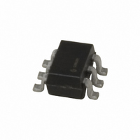
MIC2005-1.2YM6 TR Micrel Inc, MIC2005-1.2YM6 TR Datasheet - Page 14

MIC2005-1.2YM6 TR
Manufacturer Part Number
MIC2005-1.2YM6 TR
Description
IC DISTRIBUTION SW 1.2A SOT23-6
Manufacturer
Micrel Inc
Type
High Side Switchr
Specifications of MIC2005-1.2YM6 TR
Number Of Outputs
1
Rds (on)
100 mOhm
Internal Switch(s)
Yes
Current Limit
1.2A
Voltage - Input
2.5 ~ 5.5 V
Operating Temperature
-40°C ~ 85°C
Mounting Type
Surface Mount
Package / Case
SOT-23-6
Short Circuit Current Limit
1.6A
Input Voltage Range
2.5 to 5.5V
Number Of Switches
Single
Operating Temp Range
-40C to 85C
Operating Temperature Classification
Industrial
Mounting
Surface Mount
Pin Count
6
Package Type
SOT-23
Lead Free Status / RoHS Status
Lead free / RoHS Compliant
Other names
576-2589-2
MIC2005-1.2YM6 TR
MIC2005-1.2YM6TR
MIC2005-1.2YM6TR
MIC2005-1.2YM6 TR
MIC2005-1.2YM6TR
MIC2005-1.2YM6TR
January 2008
C
The C
output voltage ramp at turn-on. This input allows
designers the option of decreasing the output’s slew rate
(slowing the voltage rise) by adding an external
capacitance between the pin, C
capacitance slows the rate at which the pass FET gate
voltage increases and thus, slows both the response to
an Enable command as well as VOUT’s ascent to its
final value.
Figure 8 illustrates effect of C
and output rise time.
C
An
capacitance is a reduction in the MIC2005/2015’s ability
to quickly limit current transients or surges. A sufficiently
large capacitance can prevent both the primary and
secondary current limits from acting in time to prevent
damage to the MIC2005/2015 or the system from a
SLEW
SLEW
unavoidable
’s effect on I
SLEW
(Not present with SOT23-5 (M5))
input is provided to increase control of the
1.2
1.0
0.8
0.6
0.4
0.2
0
0
Normalized Output Current
vs. Output Voltage (2.5V)
LIMIT
0.5
OUTPUT VOLTAGE (V)
consequence
Figure 7.
1.0
Figure 8
1.5
SLEW
2.0
SLEW
of
on turn-ON delay
2.5
, and VIN. This
adding
3.0
C
SLEW
14
short circuit fault. For this reason, the upper limit on the
value of C
Kickstart (MIC2015)
Kickstart allows brief current surges to pass to the load
before the onset of normal current limiting, which
permits dynamic loads to draw bursts of energy without
sacrificing system safety.
Functionally, Kickstart is a forced override of the normal
current limiting function provided by MIC2015. The
Kickstart period is governed by an internal timer which
allows current to pass unimpeded to the load for 128ms
and then normal (primary) current limiting goes into
action.
During Kickstart a secondary current limiting circuit is
monitoring output current to prevent damage to the
MIC2015, as a hard short combined with a robust power
supply can result in currents of many tens of amperes.
This secondary current limit is nominally set at 4 Amps
and reacts immediately and independently of the
Kickstart period. Once the Kickstart timer has finished its
count the primary current limiting circuit takes over and
holds I
excessive load persists.
Once MIC2015 drops out of current limiting the Kickstart
timer initiates a lock-out period of 128ms such that no
further bursts of current above the primary current limit,
will be allowed until the lock-out period has expired.
Kickstart may be over-ridden by the thermal protection
circuit and if sufficient internal heating occurs, Kickstart
will be terminated and I
load is still present I
OUT
SLEW
to its programmed limit for as long as the
is 4nF.
Figure 9. Kickstart
OUT
OUT
I
LIMIT
, not I
0. Upon cooling, if the
KICKSTART
M9999-011708-A
(408) 944-0800
.


