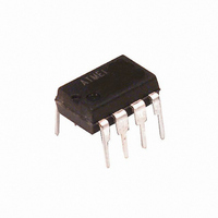
U6032B-MY Atmel, U6032B-MY Datasheet

U6032B-MY
Specifications of U6032B-MY
Related parts for U6032B-MY
U6032B-MY Summary of contents
Page 1
... Protection According to ISO/TR7637-1 (VDE 0839) 1. Description The bipolar integrated circuit U6032B is designed as a toggle switch. The device, which has a defined power-on status, can be used to control electrical loads, for example, fog lamps, high/low beam or heated windows for automotive applications. Figure 1-1. ...
Page 2
... Pin Description Pin Symbol Function 1 GND Reference point, ground 2 RELAY Relay control output 3 ON Switch-on input 4 OFF Switch-off input 5 TOGGLE Toggle input 6 OSC RC oscillator input 7 VSTAB Stabilized voltage 8 VS Supply voltage U6032B GND VS VSTAB RELAY OSC TOGGLE OFF 4 5 4771B–AUTO–11/05 ...
Page 3
... Figure 4-1. The dropping resistor, R smoothes the supply voltage at pin 510 , µ and the R C circuit is omitted Basic Circuit for 12-V Supply and Oscillator V Batt R 510 µ U6032B , limits the current thus enabling stable operation Batt U6032B Figure 3 ...
Page 4
... The debounce time Table 7-1 on page 8 20 kHz. U6032B 4 Basic Circuit for Batt are constants, e.g 1.551 when C = 470 1.284 when 4700 depends on the oscillator frequency follows shows the relationship between U6032B circuit. The resistance and frequencies from deter 4771B–AUTO–11/05 ...
Page 5
... TOGGLE Function V Batt R 1 510 µ Figure 4-4 on page Figure 4-4 on page 6). , the output stays active U6032B U6032B 6). 5 ...
Page 6
... It can be increased by connecting a 5.6 k resistor from the push-button switch to ground as shown in Figure 4-4. Figure 4-5. U6032B 6 , has ellapsed whereas the switching of pin 4 switch correspondingly leads to the 3 shows the input circuit of U6032B. It has an integrated pull-down resistor ( – where Batt Z 0.25 mA Figure 4-6 on page 7 ...
Page 7
... Parameters DIP8 Junction ambient SO8 4771B–AUTO–11/05 Increasing the Contact Current by Parallel Resistors V Batt 6032 Symbol V Batt T amb T stg T j Symbol T thJA T thJA U6032B 2 mA 5 Value 24 -40 to +125 -55 to +125 150 Value 110 160 Unit Unit K/W K/W 7 ...
Page 8
... Switching Times Debounce time Inputs ON, OFF, TOGGLE Switching threshold voltage Internal Z-diode I 3,4,5 Pull-down resistance V 3,4,5 Table 7-1. Values for C and R 2 Frequency f (Hz U6032B 8 Figure 1-1 on page Pin 510 , Table 7 for a Given Oscillator Frequency and Debounce Time 2 Debounce Time t (ms) ...
Page 9
... U6032B C (nF 1000 130 100 650 100 440 100 330 100 260 100 220 100 190 100 160 ...
Page 10
... Ordering Information Extended Type Number U6032B-MY U6032B-MFPY U6032B-MFPG3Y 9. Package Information Package SO8 Dimensions in mm U6032B 10 Package Remarks DIP8 Pb-free SO8 Tubed, Pb-free SO8 Taped and reeled, Pb-free ific a tio 5.00 4.85 1.4 0.25 0.4 0.10 1.27 3. technical drawings according to DIN specifications ...
Page 11
... Revision History Please note that the following page numbers referred to in this section refer to the specific revision mentioned, not to this document. Revision No. 4771B-AUTO-11/05 4771B–AUTO–11/05 History Put datasheet in a new template First page: Pb-free logo added Page 10: Ordering Information changed U6032B 11 ...
Page 12
... Disclaimer: The information in this document is provided in connection with Atmel products. No license, express or implied, by estoppel or otherwise, to any intellectual property right is granted by this document or in connection with the sale of Atmel products. EXCEPT AS SET FORTH IN ATMEL’S TERMS AND CONDI- TIONS OF SALE LOCATED ON ATMEL’S WEB SITE, ATMEL ASSUMES NO LIABILITY WHATSOEVER AND DISCLAIMS ANY EXPRESS, IMPLIED OR STATUTORY WARRANTY RELATING TO ITS PRODUCTS INCLUDING, BUT NOT LIMITED TO, THE IMPLIED WARRANTY OF MERCHANTABILITY, FITNESS FOR A PARTICULAR PURPOSE, OR NON-INFRINGEMENT ...


