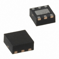
MIC2015-1.2YML TR Micrel Inc, MIC2015-1.2YML TR Datasheet - Page 23

MIC2015-1.2YML TR
Manufacturer Part Number
MIC2015-1.2YML TR
Description
IC DISTRIBUTION SW 1.2A 6-MLF
Manufacturer
Micrel Inc
Type
High Side Switchr
Datasheet
1.MIC2009YM6_TR.pdf
(29 pages)
Specifications of MIC2015-1.2YML TR
Number Of Outputs
1
Rds (on)
100 mOhm
Internal Switch(s)
Yes
Current Limit
1.2A
Voltage - Input
2.5 ~ 5.5 V
Operating Temperature
-40°C ~ 85°C
Mounting Type
Surface Mount
Package / Case
6-MLF®, QFN
Lead Free Status / RoHS Status
Lead free / RoHS Compliant
Other names
MIC2015-1.2YMLTR
MIC2015-1.2YMLTR
MIC2015-1.2YMLTR
Application Information
Setting I
The MIC2009/2019’s current limit is user programmable
and controlled by a resistor connected between the I
pin and Ground. The value of this resistor is determined
by the following equation:
or
For example:
Looking in the Electrical specifications we will find CLF
at I
For the sake of this example, we will say the typical
value of CLF at an I
equation above:
(the closest standard 1% value)
Designers should be aware that variations in the
measured I
because of small differences between individual ICs
(inherent in silicon processing) resulting in a spread of
I
value of CLF to calculate R
spread by using the minimum and maximum values of
CLF and the calculated value of R
Giving us a maximum I
February 2011
LIMIT
Micrel, Inc.
LIMIT
I
0.97A (-22%)
I
R
LIMIT_MIN
LIMIT
values. In the example above we used the typical
SET
Min
190
I
I
LIMIT_MIN
LIMIT_MAX
= 1 A.
R
R
LIMIT
SET
=
=
SET
CurrentLim
CurrentLim
LIMIT
= 196Ω
(
Ω
Table 1. CLF at I
)
=
Set I
=
=
for a given R
196
190V
196Ω
293V
1.25A
243V
I
Typ
243
LIMIT
LIMIT
R
Ω
OUT
LIMIT
itFactor(C
SET
itFactor(C
=
I
1.25A
LIMIT_TYP
=
(A)
= 1.25 A
=
. 0
of 1A is 243V. Applying the
1.5A
variation over temperature of:
SET
194
97
. We can determine I
A
4 .
LIMIT
SET
LF)
LF)
Ω
SET
Max
293
= 1A
.
resistor, will occur
I
1.5A (+20%)
LIMIT_MAX
Units
V
LIMIT
LIMIT
’s
23
I
The MIC20XX’s current limiting circuitry, during current
limiting, is designed to act as a constant current source
to the load. As the load tries to pull more than the
allotted current, V
voltage differential increases. When V
1V, I
current on the system’s power supply and to limit internal
heating of the switch.
When measuring I
dependence in mind, otherwise the measurement data
may appear to indicate a problem when none really
exists. This voltage dependence is illustrated in Figures
4 and 5.
In Figure 4, output current is measured as V
below V
below V
remains constant throughout the remainder of the test. In
LIMIT
vs. I
OUT
0.2A
0.3A
0.4A
0.5A
0.6A
0.7A
0.8A
0.9A
1.1A
1.2A
1.3A
1.4A
1.5A
I
0.1A
0.2A
0.3A
0.4A
0.5A
0.6A
0.7A
0.8A
0.9A
I
OUT
1A
OUT
IN
IN
drops below I
OUT
, with the test terminating when V
. Observe that once I
Measured
Table 2. MIC20x9A R
Table 3. MIC20x9 R
1125Ω
1928Ω
765Ω
582Ω
470Ω
395Ω
341Ω
300Ω
268Ω
243Ω
222Ω
204Ω
189Ω
176Ω
165Ω
R
993Ω
673Ω
511Ω
413Ω
346Ω
299Ω
263Ω
235Ω
R
SET
OUT
SET
OUT
it is important to bear this voltage
LIMIT
drops and the input to output
I
to reduce the drain of fault
I
0.127A
0.202A
0.281A
0.361A
0.443A
0.526A
0.610A
0.695A
0.781A
0.868A
0.956A
1.044A
1.133A
1.222A
LIMIT_MIN
0.063A
0.137A
0.216A
0.296A
0.379A
0.463A
0.548A
0.634A
0.722A
LIMIT_MIN
SET
SET
LIMIT
Table
Table
IN
MIC20xx Family
M9999-020311-D
is reached I
- V
I
I
LIMIT_MAX
0.136A
0.265A
0.391A
0.515A
0.637A
0.759A
0.880A
1.001A
1.121A
LIMIT_MAX
0.267A
0.390A
0.510A
0.629A
0.746A
0.861A
0.976A
1.089A
1.202A
1.314A
1.426A
1.537A
1.647A
1.757A
OUT
OUT
OUT
exceeds
is pulled
is 1V
OUT


