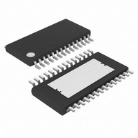
MAX1969EUI+ Maxim Integrated Products, MAX1969EUI+ Datasheet - Page 11

MAX1969EUI+
Manufacturer Part Number
MAX1969EUI+
Description
IC DRVR POWER 28-TSSOP
Manufacturer
Maxim Integrated Products
Datasheet
1.MAX1969EUI.pdf
(16 pages)
Specifications of MAX1969EUI+
Applications
Thermoelectric Cooler
Voltage - Supply
3 V ~ 5.5 V
Operating Temperature
-40°C ~ 85°C
Mounting Type
Surface Mount
Package / Case
28-TSSOP Exposed Pad, 28-eTSSOP, 28-HTSSOP
Lead Free Status / RoHS Status
Lead free / RoHS Compliant
Current - Supply
-
Lead Free Status / Rohs Status
Lead free / RoHS Compliant
The MAX1968/MAX1969 TEC drivers consist of two
switching buck regulators that operate together to
directly control TEC current. This configuration creates
a differential voltage across the TEC, allowing bidirec-
tional TEC current for controlled cooling and heating.
Controlled cooling and heating allow accurate TEC
temperature control within the tight tolerances of laser
driver specifications. The voltage at CTLI directly sets
the TEC current. An external thermal-control loop is typ-
ically used to drive CTLI. Figures 1 and 2 show exam-
ples of thermal control-loop circuits.
Switching regulators like those used in the
MAX1968/MAX1969 inherently create ripple voltage on
the output. The regulators in the MAX1968 switch in
phase and provide complementary in-phase duty cycles
so ripple waveforms at the TEC are greatly reduced. This
feature suppresses ripple currents and electrical noise at
the TEC to prevent interference with the laser diode.
FREQ sets the switching frequency of the internal oscil-
lator. With FREQ = GND, the oscillator frequency is set
to 500kHz. The oscillator frequency is 1MHz when
FREQ = V
Both the MAX1968 and MAX1969 provide control of the
maximum differential TEC voltage. Applying a voltage
to MAXV limits the maximum voltage across the TEC.
The MAX1968 provides control of the maximum positive
and negative TEC current. The voltage at MAXIP and
MAXIN sets the maximum positive and negative current
through the TEC. These current limits can be indepen-
dently controlled. The MAX1969 only controls TEC cur-
rent in one direction. The maximum TEC current is
controlled by MAXIP. Connect MAXIN to GND when
using the MAX1969.
ITEC provides a voltage output proportional to the TEC
current (I
detail:
The MAX1968/MAX1969 include an on-chip voltage ref-
erence. The 1.50V reference is accurate to 1% over
temperature. Bypass REF with 1µF to GND. REF may
be used to bias an external thermistor for temperature
sensing as shown in Figures 1 and 2.
DD
TEC
Voltage and Current-Limit Settings
V
.
ITEC
). See the Functional Diagram for more
= 1.5V + 8 x (V
______________________________________________________________________________________
Detailed Description
Power Drivers for Peltier TEC Modules
Current Monitor Output
Switching Frequency
Ripple Cancellation
Reference Output
OS1
- V
CS
)
Small surface-mount inductors are ideal for use with the
MAX1968/MAX1969. 3.3µH inductors are suitable for
most applications. Select the output inductors so that
the LC resonant frequency of the inductance and the
output capacitance is less than 1/5 the selected switch-
ing frequency. For example, 3.3µH and 1µF have a res-
onance at 87.6kHz, which is adequate for 500kHz
operation
where:
f = resonant frequency of output filter.
Decouple each power-supply input (V
PV
pins. In some applications with long distances between
the source supply and the MAX1968/MAX1969, addition-
al bypassing may be needed to stabilize the input sup-
ply. In such cases, a low-ESR electrolytic capacitor of
100µF or more at V
A compensation capacitor is needed to ensure current
control-loop stability. Select the capacitor so that the
unity-gain bandwidth of the current control loop is less
than or equal to 1/12th the resonant frequency of the out-
put filter:
where:
f
g
C
R
R
BW
C
C
m
TEC
SENSE
COMP
DD
COMP
COMP
= loop transconductance, typically 100µA/V
= loop unity gain bandwidth
2) with a 1µF ceramic capacitor close to the supply
= TEC series resistance
= value of the compensation capacitor
= sense resistor
≥
≥
⎛
⎜
⎝
⎛
⎜
⎝
f
f
g
g
BW
BW
m
m
⎞
⎟ ×
⎠
⎞
⎟ ×
⎠
⎛
⎜
⎝
⎛
⎜
⎝
DD
2
2
π
π
f
is usually sufficient.
×
×
=
12
24
(
(
R
R
2π
SENSE
SENSE
×
×
Design Procedure
R
R
1
Compensation Capacitor
SENSE
SENSE
LC
Capacitor Selection
Inductor Selection
+
+
R
R
TEC
TEC
Filter Capacitors
)
)
⎞
⎟
⎠
⎞
⎟
⎠
(
(
For MAX
For MAX
DD
, PV
1968
1969
DD
11
1,
)
)


