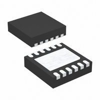
LTC2953IDD-2#TRPBF Linear Technology, LTC2953IDD-2#TRPBF Datasheet - Page 14

LTC2953IDD-2#TRPBF
Manufacturer Part Number
LTC2953IDD-2#TRPBF
Description
IC PB ON/OFF CONTROLLER 12DFN
Manufacturer
Linear Technology
Datasheet
1.LTC2953CDD-1PBF.pdf
(20 pages)
Specifications of LTC2953IDD-2#TRPBF
Applications
Push Button, On/Off Controller
Voltage - Supply
2.7 V ~ 27 V
Current - Supply
14µA
Operating Temperature
-40°C ~ 85°C
Mounting Type
Surface Mount
Package / Case
12-DFN
Lead Free Status / RoHS Status
Lead free / RoHS Compliant
Voltage - Input
-
Available stocks
Company
Part Number
Manufacturer
Quantity
Price
LTC2953
APPLICATIONS INFORMATION
(LTC2953-1)
Aborted Power On Sequence
The LTC2953 provides an internal 512ms timer to detect
when a system fails to power on properly. A power on
sequence begins by debouncing the ⎯ P ⎯ B input. After the
enable pin is subsequently asserted, the LTC2953 starts
the 512ms blanking timer (t
input is not driven high within this 512ms time window,
the enable pin is immediately released, thus turning off
system power. This failsafe feature prevents a user from
turning on the device when the circuits driving the ⎯ K ⎯ I ⎯ L ⎯ L
input do not respond within 512ms after enable has been
asserted. See Figure 12.
μP Turns Off System Power During Normal Operation
Once the system has powered on and is operating normally,
the μP can turn off power by asserting the ⎯ K ⎯ I ⎯ L ⎯ L input low.
See Figure 13.
DUAL FUNCTION BATTERY SUPERVISOR
The LTC2953 provides two comparators for battery
monitoring: an uncommitted power fail comparator and
a latched low battery comparator with μP interrupt. The
application shown in Figure 14 monitors a 2 cell Li-Ion
battery stack.
14
KILL
PB
EN
Figure 12. Aborted Power On Sequence, ⎯ K ⎯ I ⎯ L ⎯ L
Remaining Low Aborts Power On Sequence
t
DB, ON
SYSTEM FAILS TO SET KILL HIGH
KILL, ON BLANK
PB, UVLO AND KILL
TURN ON ABORTED
t
KILL, ON BLANK
IGNORED
). If the ⎯ K ⎯ I ⎯ L ⎯ L
2953 F12
(LTC2953-1)
Power Fail Comparator
This comparator provides real time threshold information
and can serve as the fi rst warning of a decaying battery or
supply. The ⎯ P ⎯ F ⎯ O output is driven low when the PFI input
voltage drops below its falling threshold (0.5V) and is
high impedance when PFI rises above its rising threshold
(0.504V). The low leakage, high voltage PFI input (10nA,
maximum) allows the use of large valued external resistors,
which lowers system current consumption.
UVLO Comparator
The under voltage lockout comparator performs three
functions: a) interrupts the μP when a supply glitch drives
the UVLO voltage below its falling threshold (0.5V) for
longer than 32ms, followed by b) forces system power
off when the UVLO voltage falls below its falling threshold
(0.5V) for t
system power on) output if UVLO voltage is below its fall-
ing threshold (0.5V) during system power on. See Figures
15A and 15B.
The low leakage (10nA, maximum), high voltage UVLO
input allows the use of large valued external resistors.
See Figure 14.
KILL
EN
PD, Min
Figure 13. μP Turns Off System Power
+ t
PDT
, c) locks out the enable (prevents
t
KILL(PD)
SYSTEM SETS KILL LOW
SYSTEM POWER OFF
2953f
2953 F13


