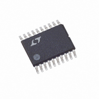
LTC2922IF-2.5 Linear Technology, LTC2922IF-2.5 Datasheet - Page 14

LTC2922IF-2.5
Manufacturer Part Number
LTC2922IF-2.5
Description
IC 5 PWR SUPPLY MONITOR 20TSSOP
Manufacturer
Linear Technology
Datasheet
1.LTC2921CGN-3.3.pdf
(20 pages)
Specifications of LTC2922IF-2.5
Applications
Five Power Supply Monitor
Voltage - Supply
2.37 V ~ 2.63 V
Current - Supply
2mA
Operating Temperature
-40°C ~ 85°C
Mounting Type
Surface Mount
Package / Case
20-TSSOP
Lead Free Status / RoHS Status
Contains lead / RoHS non-compliant
Voltage - Input
-
LTC2921/LTC2922 Series
APPLICATIO S I FOR ATIO
pin has fully ramped up. The switches are N-channel
MOSFETs whose gates are ramped from ground to V
at a nominal rate of 8V/ms. The PG pin is activated upon
completion of the TIMER delay cycle that follows GATE
ramp-up and remote sense switch activation. When con-
ditions indicate a supply disconnect, the switches shut off
in less than 10 s.
Figure 10 shows an example of how to connect a switch to
remote sense the load voltage. Although only one remote
sense switch is referred to in this section, the calculations
and comments apply to all.
Before the activation of Q1 and the internal switch, resistor
R
output voltage and its feedback network (R
Once Q1 activates, the supply energizes the load. When
the internal switch turns on, it provides a remote sense
path between the load voltage and the converter’s feed-
back network.
14
X1
provides a direct path between the DC/DC converter’s
Figure 9. PG Pin as Sequenced N-Channel Gate Driver
V
SRC0
V
V
SRC5
SRC0
LTC2922
ENABLE
ENABLE
LTC2922
Figure 8. PG Pin as Logic Output
V
V
CC
PG
CC
PG
R
R
SENSE
SENSE
SENSE
U
SENSE
4 A
4 A
V
PUMP
V
U
PUMP
2921/22 F08
GATE
2921/22 F09
GND
GATE
GND
PG
PG
Q0
Q0
W
R
R
10
PG
R
10
G0
C
G0
C
GATE
GATE
Q5
RESET
R
10
G5
C
C
PG
Y1
V
V
V
L5
L0
L0
U
and R
PUMP
Z1
).
To choose a value for resistor R
sense switch connection equivalent network in Figure 11.
Resistor R
resistor R
nal switch.
To allow the load voltage to dominate the feedback to the
converter when the internal switch is closed, make R
R
with R
than (R
flows through the external N-channel FET, choose (R
R
amount to:
Approach the selection of R
the DC/DC converter feedback based on the resistive
divider formed by R
supply voltage value. When the resistor values satisfy
Equation 11, Equations 12 through 15 are valid.
Figure 11. Remote Sense Switch Connection Equivalent Network
FB1(ON)
FB1(ON)
R
Figure 10. Automatic Remote Sense Switching Connection
Q1(ON)
Y1
CONVERTER
CONVERTER
Y1
DC/DC
DC/DC
. To set the converter feedback ratio accurately
) >> R
and R
FB1(ON)
V
V
+ R
GND
GND
, R
OUT
V
Q1(ON)
OUT
V
FB
FB
FB(ON)
Z1
R
Z1
Z1
Q1(ON)
). To ensure that most of the load current
V
V
represents the on-resistance of the inter-
, make both R
SRC1
represents the on-resistance of Q1, and
SRC1
R
Z1
R
R
R
Y1
Y1
<< R
X1
R
Y1
X1
. Summarized, these requirements
V
V
S1
R
R
S1
and R
B1
A1
X1
I
I
DS1
Q1
X1
<< (R
in the following way: design
V1
S1
Z1
S1
X1
LTC2922
LTC2922
R
R
X1
with V
FB1(ON)
Y1
Q1(ON)
GND
and R
, consider the remote
+ R
GATE
D1
D1
FB1(ON)
Z1
S1
Q1
)
at the desired
R
10
C
G1
GATE
V
LOAD
2921/22 F11
much less
L1
V
LOAD
2921/22 F10
L1
I
L1
X1
29212fa
(11)
X1
>>
+


