AD637JD Analog Devices Inc, AD637JD Datasheet

IC RMS/DC CONV PRECISION 14-CDIP

AD637JD

Manufacturer Part Number
AD637JD
Description
IC RMS/DC CONV PRECISION 14-CDIP
Manufacturer
Analog Devices Inc
Datasheets

Specifications of AD637JD

Rohs Status
RoHS non-compliant
Current - Supply
2.2mA
Voltage - Supply
±3.0V ~ 18V
Mounting Type
Through Hole
Package / Case
14-CDIP (0.300", 7.62mm)
Accuracy %
0.04%
Bandwidth
8MHz
Supply Current
2.2mA
Power Dissipation Pd
108mW
Supply Voltage Range
± 3V To ± 18V
Digital Ic Case Style
DIP
No. Of Pins
14
Operating Temperature Range
0°C
For Use With
AD637-EVALZ - BOARD EVALUATION FOR AD637
Lead Free Status / RoHS Status
Contains lead / RoHS non-compliant

Available stocks

Company
Part Number
Manufacturer
Quantity
Price
Part Number:
AD637JD
Manufacturer:
MIC
Quantity:
185
Part Number:
AD637JD
Manufacturer:
ADI
Quantity:
627
Part Number:
AD637JD
Manufacturer:
ADI/亚德诺
Quantity:
20 000
Part Number:
AD637JDZ
Manufacturer:
ADI
Quantity:
627
a
PRODUCT DESCRIPTION
The AD637 is a complete high accuracy monolithic rms-to-dc
converter that computes the true rms value of any complex wave-
form. It offers performance that is unprecedented in integrated
circuit rms-to-dc converters and comparable to discrete and
modular techniques in accuracy, bandwidth, and dynamic range.
A crest factor compensation scheme in the AD637 permits mea-
surements of signals with crest factors of up to 10 with less than
1% additional error. The circuit’s wide bandwidth permits the
measurement of signals up to 600 kHz with inputs of 200 mV
rms and up to 8 MHz when the input levels are above 1 V rms.
As with previous monolithic rms converters from Analog Devices,
the AD637 has an auxiliary dB output available to the user. The
logarithm of the rms output signal is brought out to a separate
pin, allowing direct dB measurement with a useful range of
60 dB. An externally programmed reference current allows the
user to select the 0 dB reference voltage to correspond to any
level between 0.1 V and 2.0 V rms.
A chip select connection on the AD637 permits the user to de-
crease the supply current from 2.2 mA to 350 µA during periods
when the rms function is not in use. This feature facilitates the
addition of precision rms measurement to remote or hand-held
applications where minimum power consumption is critical. In
addition when the AD637 is powered down the output goes to a
high impedance state. This allows several AD637s to be tied
together to form a wideband true rms multiplexer.
The input circuitry of the AD637 is protected from overload
voltages that are in excess of the supply levels. The inputs will
not be damaged by input signals if the supply voltages are lost.
The AD637 is available in two accuracy grades (J and K) for
commercial (0°C to 70°C) temperature range applications;
two accuracy grades (A and B) for industrial (–40°C to +85°C)
applications; and one (S) rated over the –55°C to +125°C tem-
perature range. All versions are available in hermetically sealed,
14-lead side brazed ceramic DIPs as well as low cost cerdip
packages. A 16-lead SOIC package is also available.
PRODUCT HIGHLIGHTS
1. The AD637 computes the true root-mean-square, mean-
2. The AD637 is laser wafer trimmed to achieve rated
3. The chip select feature of the AD637 permits the user to
4. The on-chip buffer amplifier can be used either as an input
1
2
3
4
5
6
7
square, or absolute value of any complex ac (or ac plus dc)
input waveform and gives an equivalent dc output voltage.
The true rms value of a waveform is more useful than an
average rectified signal since it relates directly to the power of
the signal. The rms value of a statistical signal is also related
to the standard deviation of the signal.
performance without external trimming. The only external
component required is a capacitor that sets the averaging
time period. The value of this capacitor also determines
low-frequency accuracy, ripple level, and settling time.
power down the device during periods of nonuse, thereby
decreasing battery drain in remote or hand-held applications.
buffer or in an active filter configuration. The filter can be
used to reduce the amount of ac ripple, thereby increasing
the accuracy of the measurement.
Ceramic DIP (D) and
25k
Cerdip (Q) Packages
SECTION
BIAS
BUFFER
FUNCTIONAL BLOCK DIAGRAMS
High Precision, Wideband
SQUARER/DIVIDER
ABSOLUTE
VALUE
RMS-to-DC Converter
FILTER
AD637
25k
14
13
12
11
10
9
8
1
2
3
4
6
5
7
8
25k
SECTION
SOIC (R) Package
BIAS
BUFFER
SQUARER/DIVIDER
AD637
ABSOLUTE
VALUE
FILTER
AD637
25k
15
14
13
11
10
16
12
9

Related parts for AD637JD

AD637JD Summary of contents

Page 1

PRODUCT DESCRIPTION The AD637 is a complete high accuracy monolithic rms-to-dc converter that computes the true rms value of any complex wave- form. It offers performance that is unprecedented in integrated circuit rms-to-dc converters and comparable to discrete and ...

Page 2

AD637–SPECIFICATIONS AD637J/A Model Min TRANSFER FUNCTION V CONVERSION ACCURACY 1 Total Error, Internal Trim (Fig MIN MAX vs. Supply +300 mV IN vs. Supply, – –300 Reversal Error ...

Page 3

Model Min CHIP SELECT PROVISION (CS) RMS “ON” Level Open or 2.4 V < V RMS “OFF” Level V < 0 Chip Select OUT CS “Low” “High” Zero 10 µs + ((25 kΩ) On ...

Page 4

... Although the AD637 features proprietary ESD protection circuitry, permanent damage may occur on devices subjected to high energy electrostatic discharges. Therefore, proper ESD precautions are recommended to avoid performance degradation or loss of functionality. Model AD637AR AD637BR AD637AQ AD637BQ AD637JD AD637JD/+ AD637KD AD637KD/+ AD637JQ AD637KQ AD637JR AD637JR-REEL AD637JR-REEL7 AD637KR ...

Page 5

DIP 1 BUFF COMMON 3 AD637 OUTPUT OFFSET 4 TOP VIEW (Not to Scale DEN INPUT 6 dB OUTPUT CONNECT 14-Lead DIP Pin No. Mnemonic 1 BUFF ...

Page 6

AD637 FUNCTIONAL DESCRIPTION The AD637 embodies an implicit solution of the rms equation that overcomes the inherent limitations of straightforward rms computation. The actual computation performed by the AD637 follows the equation  rms Avg  ...

Page 7

CHIP SELECT The AD637 includes a chip select feature that allows the user to decrease the quiescent current of the device from 2 350 µA. This is done by driving the CS, Pin 5, to below 0.2 V ...

Page 8

AD637 100 10 PEAK RIPPLE 1.0 DC ERROR 0.1 10 100 SINEWAVE INPUT FREQUENCY – Hz × µ The ac ripple component of averaging error can be greatly reduced by increasing the value of the averaging capacitor. There are two ...

Page 9

VALUES OF C AND 1% SETTLING TIME FOR STATED % OF READING AVERAGING ERROR 2 POLL SALLEN-KEY FILTER 10 %dc ERROR + % PEAK RIPPLE ACCURACY COMPONENT TOLERANCE 1.0 0.1 0. 100 1k INPUT FREQUENCY – Hz ...

Page 10

AD637 Figure curve of additional reading error for the AD637 for a 1 volt rms input signal with crest factors from 1 to 11. A rectangular pulse train (pulsewidth 100 µs) was used for this test since ...

Page 11

NOTE: VALUES CHOSEN TO GIVE 0. OUTPUT 1M OFFSET 50k 4 ADJUST 5 – CONNECT dB CALIBRATION 1. Set 1.00 V rms ...

Page 12

AD637 EXPANDABLE BUFFER AD637 IC1 1 14 ABSOLUTE VALUE 3 12 BIAS SECTION SQUARER/DIVIDER 25k – 25k 9 6 100pF FILTER 7 8 10k BUFFER AD637 IC2 1 14 ABSOLUTE 2 ...

Page 13

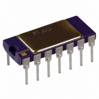
TO-116 Package (D-14) 0.005 (0.13) MIN 0.098 (2.49) MAX 14 8 0.310 (7.87) 0.220 (5.59 PIN 1 0.060 (1.52) 0.785 (19.94) MAX 0.015 (0.38) 0.200 (5.08) MAX 0.150 0.200 (5.08) (3.81) MAX 0.125 (3.18) 0.023 (0.58) 0.100 0.070 ...

Page 14

AD637 Revision History Location Data Sheet changed from REV REV. F. Edits to ORDERING GUIDE . . . . . . . . . . . . . . . . . . . . . . . ...

Page 15

...

Page 16

...

Related keywords