AD637JD/+ Analog Devices Inc, AD637JD/+ Datasheet - Page 14
AD637JD/+
Manufacturer Part Number
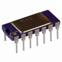
AD637JD/+
Description
IC RMS/DC CONV PRECISION 14-CDIP
Manufacturer
Analog Devices Inc
Datasheet
1.AD637JRZ.pdf
(20 pages)
Specifications of AD637JD/+
Rohs Status
RoHS non-compliant
Current - Supply
2.2mA
Voltage - Supply
±3.0V ~ 18V
Mounting Type
Through Hole
Package / Case
14-CDIP (0.300", 7.62mm)


LOW FREQUENCY MEASUREMENTS
If the frequencies of the signals to be measured are below 10 Hz,
the value of the averaging capacitor required to deliver even 1%
averaging error in the standard rms connection becomes
extremely large. Figure 21 shows an alternative method of
obtaining low frequency rms measurements. The averaging
time constant is determined by the product of R and C
this circuit, 0.5 sec/μF of C
reduction in the value of the averaging capacitor, permitting the
use of high quality tantalum capacitors. It is suggested that the
2-pole, Sallen-Key filter shown in Figure 21 be used to obtain a
low ripple level and minimize the value of the averaging
capacitor.
If the frequency of interest is below 1 Hz, or if the value of the
averaging capacitor is still too large, the 20:1 ratio can be
increased. This is accomplished by increasing the value of R.
If this is done, it is suggested that a low input current, low offset
voltage amplifier, such as the AD548, be used instead of the
internal buffer amplifier. This is necessary to minimize the
offset error introduced by the combination of amplifier input
currents and the larger resistance.
AD637
OUTPUT
ADJUST
OFFSET
NOTES
1. VALUES CHOSEN TO GIVE 0.1% AVERAGING ERROR @ 1Hz.
2. NC = NO CONNECT.
50kΩ
+V
–V
S
S
1MΩ
AV
. This circuit permits a 20:1
+V
4.7kΩ
S
1
2
3
4
5
6
7
BUFF IN
COMMON
OUTPUT
OFFSET
DEN
INPUT
dB OUTPUT
NC
CS
25kΩ
Figure 21. AD637 as a Low Frequency RMS Converter
SECTION
BIAS
BUFFER
AV1
C
3.3µF
AV1
, in
SQUARER/DIVIDER
499kΩ 1%
Rev. K | Page 14 of 20
AD637
ABSOLUTE
R
VALUE
FILTER
25kΩ
BUFF
VECTOR SUMMATION
Vector summation can be accomplished through the use of two
AD637s, as shown in Figure 22. Here, the averaging capacitors
are omitted (nominal 100 pF capacitors are used to ensure
stability of the filter amplifier), and the outputs are summed as
shown. The output of the circuit is
This concept can be expanded to include additional terms by
feeding the signal from Pin 9 of each additional AD637 through
a 10 kΩ resistor to the summing junction of the AD711 and
tying all of the denominator inputs (Pin 6) together.
If C
If the averaging capacitor is included on both IC1 and IC2, the
output is
This circuit has a dynamic range of 10 V to 10 mV and is
limited only by the 0.5 mV offset voltage of the AD637.
The useful bandwidth is 100 kHz.
OUT
C
+V
–V
V
NC
AV
IN
S
S
AV
V
14
13
12
11
10
9
8
+
is added to IC1 in this configuration, then the output is
OUT
V
V
3.3MΩ
X
V
X
100µF
+V
–V
OUT
2
2
=
+
S
+
S
SIGNAL
INPUT
V
V
V
Y
3.3MΩ
Y
2
X
2
1µF
2
+
V RMS
1µF
V
V
IN
Y
2
2
3
2
6.8MΩ
AD548JN
1000pF
V+
V–
4
7
6
V RMS OUTPUT
FILTERED
Related parts for AD637JD/+
Image
Part Number
Description
Manufacturer
Datasheet
Request
R

Part Number:
Description:
BOARD EVALUATION FOR AD637
Manufacturer:
Analog Devices Inc
Datasheet:

Part Number:
Description:
±1.7g Dual-Axis IMEMS Accelerometer Evaluation Board
Manufacturer:
Analog Devices Inc
Datasheet:
Part Number:
Description:
Inertial Sensor Evaluation System
Manufacturer:
Analog Devices Inc
Datasheet:
Part Number:
Description:
Manufacturer:
Analog Devices Inc
Datasheet:
Part Number:
Description:
Manufacturer:
Analog Devices Inc
Datasheet:
Part Number:
Description:
Manufacturer:
Analog Devices Inc
Datasheet:
Part Number:
Description:
Manufacturer:
Analog Devices Inc
Datasheet:
Part Number:
Description:
Manufacturer:
Analog Devices Inc
Datasheet:
Part Number:
Description:
Manufacturer:
Analog Devices Inc
Datasheet:
Part Number:
Description:
Manufacturer:
Analog Devices Inc
Datasheet:
Part Number:
Description:
Manufacturer:
Analog Devices Inc
Datasheet:
Part Number:
Description:
Manufacturer:
Analog Devices Inc
Datasheet:
Part Number:
Description:
Manufacturer:
Analog Devices Inc
Datasheet: