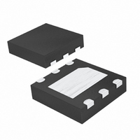
MAX6625RMTT+T Maxim Integrated Products, MAX6625RMTT+T Datasheet - Page 3

MAX6625RMTT+T
Manufacturer Part Number
MAX6625RMTT+T
Description
IC TEMP SENSOR I2C 6-TDFN
Manufacturer
Maxim Integrated Products
Datasheet
1.MAX6625PMTTT.pdf
(17 pages)
Specifications of MAX6625RMTT+T
Function
Temp Monitoring System (Sensor)
Topology
ADC, Comparator, Register Bank
Sensor Type
Internal
Sensing Temperature
-55°C ~ 125°C
Output Type
I²C™/SMBus™
Output Alarm
Yes
Output Fan
Yes
Voltage - Supply
3 V ~ 5.5 V
Operating Temperature
-55°C ~ 125°C
Mounting Type
Surface Mount
Package / Case
6-TDFN Exposed Pad
Full Temp Accuracy
+/- 1 C
Digital Output - Bus Interface
Serial (I2C)
Digital Output - Number Of Bits
9 bit
Maximum Operating Temperature
+ 125 C
Minimum Operating Temperature
- 55 C
Lead Free Status / RoHS Status
Lead free / RoHS Compliant
Other names
MAX6625RMTT+T
MAX6625RMTT+TTR
MAX6625RMTT+TTR
ELECTRICAL CHARACTERISTICS (continued)
(+3V ≤ V
Note 2: Guaranteed by design and characterization to ±5 sigma.
Note 3: Quantization error not included in specifications for temperature accuracy.
Note 4: Output current should be minimized for best temperature accuracy. Power dissipation within the MAX6625/MAX6626 causes
Note 5: A master device must provide a hold time of at least 300ns for the SDA signal in order to bridge the undefined region of
Note 6: C
Note 7: Input filters on SDA, SCL, and ADD suppress noise spikes less than 50ns.
Figure 1. Serial Bus Timing
Input High Leakage Current
Input Low Leakage Current
Input Capacitance
Output Low Voltage
Output High Current
I
Serial Clock Frequency
Bus Free Time Between STOP
and START Conditions
START Condition Hold Time
STOP Condition Setup Time
Clock Low Period
Clock High Period
Data Setup Time
Data Hold Time
Maximum Receive SCL/SDA
Rise Time
Minimum Receive SCL/SDA
Rise Time
Maximum Receive SCL/SDA
Fall Time
Minimum Receive SCL/SDA
Fall Time
Transmit SDA Fall Time
Pulse Width of Suppressed
Spike
2
C-COMPATIBLE TIMING
S
self-heating and temperature drift; see the Thermal Considerations section.
SCL’s falling edge.
B
≤ +5.5V, T
PARAMETER
= total capacitance of one bus line in pF. Tested with C
SCL
SDA
I
2
C-Compatible Serial Interface in a SOT23
A =
_______________________________________________________________________________________
t
HD:STA
-55°C to +125°C, unless otherwise noted.)
9-Bit/12-Bit Temperature Sensors with
t
F
SYMBOL
t
t
t
t
HD:DAT
HD:STA
SU:STO
SU:DAT
t
t
t
f
HIGH
V
C
I
LOW
BUF
SCL
t
I
I
OH
t
t
t
t
t
SP
IH
IL
OL
R
R
F
F
F
t
IN
LOW
t
SU:DAT
V
V
I
V
(Note 5)
(Note 6)
(Note 6)
(Note 6)
(Note 6)
C
(Note 7)
OL
IN
IN
OH
B
= 400pF, I
= +5V
= 0
= 3mA
= 5V
t
R
t
HIGH
O
CONDITIONS
= 3mA (Note 6)
B
= 400pF.
t
HD:DAT
0.1C
t
20 +
MIN
SU:STO
100
DC
1.3
0.6
0.6
1.3
0.6
0
B
0.1C
0.1C
20 +
20 +
TYP
300
300
10
50
t
BUF
B
B
MAX
400
250
0.4
0.9
±1
±1
1
UNITS
kHz
µA
µA
µA
pF
µs
µs
µs
µs
µs
ns
µs
ns
ns
ns
ns
ns
ns
V
3


