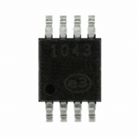
EMC1043-2-ACZL-TR SMSC, EMC1043-2-ACZL-TR Datasheet - Page 9

EMC1043-2-ACZL-TR
Manufacturer Part Number
EMC1043-2-ACZL-TR
Description
IC TEMP SNSR TRIPLE REMOTE 8MSOP
Manufacturer
SMSC
Specifications of EMC1043-2-ACZL-TR
Function
Temp Monitoring System (Sensor)
Topology
ADC (Sigma Delta), Register Bank
Sensor Type
External & Internal
Sensing Temperature
-40°C ~ 125°C, External Sensor
Output Type
SMBus™
Output Alarm
No
Output Fan
Yes
Voltage - Supply
3 V ~ 3.6 V
Operating Temperature
-40°C ~ 125°C
Mounting Type
Surface Mount
Package / Case
8-MSOP, Micro8™, 8-uMAX, 8-uSOP,
For Use With
638-1039 - BOARD EVALUATION FOR EMC1043
Lead Free Status / RoHS Status
Lead free / RoHS Compliant
Other names
638-1069-2
Available stocks
Company
Part Number
Manufacturer
Quantity
Price
Part Number:
EMC1043-2-ACZL-TR
Manufacturer:
SMSC
Quantity:
20 000
START
1°C Triple Temperature Sensor with Beta Compensation and Hotter of Two Zones
Datasheet
SMSC EMC1043
2.3
2.3.1
2.3.2
START
1
SMCLK
SMDATA
ADDRESS
SLAVE
Note 2.1
Note 2.2
A host controller, such as an SMSC I/O controller, communicates with the EMC1043 via the two wire
serial interface named SMBus. The SMBus interface is used to read and write registers in the
EMC1043, which is a slave-only device. A detailed timing diagram is shown in
The EMC1043 implements a subset of the SMBus specification and supports Write Byte, Read Byte,
Send Byte, and Receive Byte protocols as shown. In the tables that describe the protocol, the “gray”
columns indicate that the slave is driving the bus.
All of the below protocols use the following convention:
Write Byte
The Write Byte is used to write one byte of data to the registers as shown in
Read Byte
The Read Byte protocol is used to read one byte of data from the registers as shown in
System Management Bus Interface Protocol
SLAVE ADDRESS
P
WR
T
BUF
7
300nS rise time max is required for 400kHz bus operation. For lower clock frequencies,
the maximum rise time is (0.1/F
See SMSC Applications for Application Notes and Guidelines when measuring GPU
processor diodes and CPU processor diodes.
S
ACK
Figure 2.1 System Management Bus Timing Diagram
T
T
S - Start Condition
HD:STA
LOW
COMMAND
T
# of bits sent
R
WR
DATA SENT
TO DEVICE
Table 2.3 Write Byte Protocol
1
Table 2.4 Read Byte Protocol
T
HIGH
T
HD:DAT
DATASHEET
ACK
ACK
1
T
SU:DAT
T
F
9
START
SMB
DATA SENT TO
# of bits sent
COMMAND
THE HOST
)+50nS
8
ADDRESS
SLAVE
S
T
SU:STA
ACK
T
1
HD:STA
RD
P - Stop Condition
ACK
DATA
8
Table
DATA
Figure
Revision 1.44 (04-14-08)
T
SU:STO
ACK
2.3.
1
2.1.
NACK
Table
P
STOP
2.4.
1
STOP


