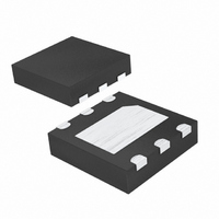
MAX6642ATT92+T Maxim Integrated Products, MAX6642ATT92+T Datasheet - Page 5

MAX6642ATT92+T
Manufacturer Part Number
MAX6642ATT92+T
Description
IC TEMP SENSOR SMBUS 6-TDFN
Manufacturer
Maxim Integrated Products
Datasheet
1.MAX6642ATT90T.pdf
(14 pages)
Specifications of MAX6642ATT92+T
Function
Temp Monitoring System (Sensor)
Topology
ADC, Multiplexer, Register Bank
Sensor Type
External & Internal
Sensing Temperature
-40°C ~ 125°C, 0°C ~ 150°C
Output Type
I²C™/SMBus™
Output Alarm
Yes
Output Fan
No
Voltage - Supply
3 V ~ 5.5 V
Operating Temperature
-40°C ~ 125°C
Mounting Type
Surface Mount
Package / Case
6-TDFN Exposed Pad
Lead Free Status / RoHS Status
Lead free / RoHS Compliant
Other names
MAX6642ATT92+T
MAX6642ATT92+TTR
MAX6642ATT92+TTR
The MAX6642 is a temperature sensor for local
and remote temperature-monitoring applications.
Communication with the MAX6642 occurs through the
SMBus-compatible serial interface and dedicated alert
pins. ALERT asserts if the measured local or remote
temperature is greater than the software-programmed
ALERT limit.
The MAX6642 converts temperatures to digital data
either at a programmed rate of eight conversions per
second or in single conversions. Temperature data is
represented by 8 data bits (at addresses 00h and 01h),
with the LSB equal to +1°C and the MSB equal to
+128°C. Two additional bits of remote temperature data
are available in the “extended” register at address 10h
and 11h (Table 2) providing resolution of +0.25°C.
The averaging ADC integrates over a 60ms period
(each channel, typ), with excellent noise rejection.
The multiplexer automatically steers bias currents
through the remote and local diodes. The ADC and
associated circuitry measure each diode’s forward volt-
age and compute the temperature based on this volt-
age. Both channels are automatically converted once
the conversion process has started, either in free-run-
ning or single-shot mode. If one of the two channels is
not used, the device still performs both measurements,
and the user can ignore the results of the unused chan-
nel. If the remote-diode channel is unused, connect
DXP to GND rather than leaving DXP open.
The conversion time per channel (remote and internal)
is 125ms. If both channels are being used, then each
channel is converted four times per second. If the
external conversion-only option is selected, then the
Temperature Sensor with Overtemperature Alarm
PIN
—
1
2
3
4
5
6
ALERT
NAME
SCLK
GND
SDA
V
DXP
EP
CC
_______________________________________________________________________________________
Supply Voltage Input, +3V to +5.5V. Bypass V
recommended but not required for additional noise filtering.
Ground
Combined Remote-Diode Current Source and ADC Input for Remote-Diode Channel. Place a 2200pF
capacitor between DXP and GND for noise filtering.
SMBus Serial-Clock Input. May be pulled up to +5.5V regardless of V
SMBus Serial-Data Input/Output, Open Drain. May be pulled up to +5.5V regardless of V
SMBus Alert (Interrupt) Output, Open Drain. ALERT asserts when temperature exceeds user-set limits. See
the ALERT Interrupts section.
Exposed Pad. Internally connected to GND. Connect to a PCB ground pad for optimal performance. Not
intended as an electrical connection point.
Detailed Description
±1°C, SMBus-Compatible Remote/Local
ADC and Multiplexer
remote temperature is measured eight times per sec-
ond. The results of the previous conversion are always
available, even if the ADC is busy.
Standby mode reduces the supply current to less than
10µA by disabling the ADC and timing circuitry. Enter
standby mode by setting the RUN bit to 1 in the config-
uration byte register (Table 4). All data is retained in
memory, and the SMBus interface is active and listen-
ing for SMBus commands. Standby mode is not a shut-
down mode. With activity on the SMBus, the device
draws more supply current (see the Typical Operating
Characteristics ). In standby mode, the MAX6642 can
be forced to perform ADC conversions through the
one-shot command, regardless of the RUN bit status.
If a standby command is received while a conversion is
in progress, the conversion cycle is truncated, and the
data from that conversion is not latched into a tempera-
ture register. The previous data is not changed and
remains available.
Supply-current drain during the 125ms conversion peri-
od is 500µA (typ). In standby mode, supply current
drops to 3µA (typ).
From a software perspective, the MAX6642 appears as
a set of byte-wide registers that contain temperature
data, alarm threshold values, and control bits. A stan-
dard SMBus-compatible 2-wire serial interface is used
to read temperature data and write control bits and
alarm threshold data.
The MAX6642 employs four standard SMBus protocols:
Write Byte, Read Byte, Send Byte, and Receive Byte.
(Figures 1, 2, and 3). The shorter Receive Byte protocol
allows quicker transfers, provided that the correct data
CC
FUNCTION
to GND with a 0.1µF capacitor. A 47Ω series resistor is
CC
Low-Power Standby Mode
.
SMBus Digital Interface
Pin Description
CC
.
5


