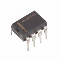
DS1631+ Maxim Integrated Products, DS1631+ Datasheet - Page 10

DS1631+
Manufacturer Part Number
DS1631+
Description
IC THERMOMETER DIG HI-PREC 8-DIP
Manufacturer
Maxim Integrated Products
Datasheet
1.DS1631U.pdf
(15 pages)
Specifications of DS1631+
Function
Thermometer, Thermostat
Topology
ADC (Sigma Delta), Comparator, Register Bank
Sensor Type
Internal
Sensing Temperature
-55°C ~ 125°C
Output Type
I²C™/SMBus™
Output Alarm
Yes
Output Fan
No
Voltage - Supply
2.7 V ~ 5.5 V
Operating Temperature
-55°C ~ 125°C
Mounting Type
Through Hole
Package / Case
8-DIP (0.300", 7.62mm)
Full Temp Accuracy
+/- 2 C
Digital Output - Bus Interface
Serial (2-Wire)
Digital Output - Number Of Bits
12 bit
Maximum Operating Temperature
+ 125 C
Minimum Operating Temperature
- 55 C
Ic Output Type
Digital
Sensing Accuracy Range
± 0.5°C
Supply Current
1.25mA
Supply Voltage Range
2.7V To 5.5V
Resolution (bits)
12bit
Sensor Case Style
DIP
No. Of Pins
8
Accuracy %
0.5°C
Rohs Compliant
Yes
Lead Free Status / RoHS Status
Lead free / RoHS Compliant
*Stored in EEPROM
Table 6. RESOLUTION CONFIGURATION
Table 5. CONFIGURATION REGISTER BIT DESCRIPTIONS
DONE—Temperature
(Read Only)
THF—Temperature High Flag
(Read/Write)
TLF—Temperature Low Flag
(Read/Write)
NVB—NV Memory Busy
(Read Only)
R1—Resolution Bit 1
(Read/Write)
R0—Resolution Bit 0
(Read/Write)
POL*—T
(Read/Write)
1SHOT*—Conversion Mode
(Read/Write)
(USER ACCESS)
Conversion Done
BIT NAME
OUT
Polarity
R1
0
0
1
1
R0
0
1
0
1
Power-up state = 1.
DONE = 0. Temperature conversion is in progress.
DONE = 1. Temperature conversion is complete.
Power-up state = 0.
THF = 0. The measured temperature has not exceeded the value
stored in the T
THF = 1. At some point since power-up the measured temperature
has been higher than the value stored in the T
a 1 until it is overwritten with a 0 by the user, the power is cycled, or
a Software POR command is issued.
Power-up state = 0.
TLF = 0. The measured temperature has not been lower than the
value stored in the T
TLF = 1. At some point since power-up the measured temperature
has been lower than the value stored in the T
1 until it is overwritten with a 0 by the user, the power is cycled, or a
Software POR command is issued.
Power-up state = 0.
NVB = 1. A write to EEPROM memory is in progress.
NVB = 0. NV memory is not busy.
Power-up state = 1.
Sets conversion, T
Power-up state = 1.
Sets conversion, T
Power-up state = last value written to this bit. Factory setting = 0.
POL = 1. T
POL = 0. T
Power-up state = last value written to this bit. Factory setting = 0.
1SHOT = 1. One-Shot Mode. The Start Convert T command initiates
a single temperature conversion and then the device goes into a low-
power standby state.
1SHOT = 0. Continuous Conversion Mode. The Start Convert T
command initiates continuous temperature conversions.
RESOLUTION
(BIT)
10
11
12
OUT
OUT
9
10 of 15
H
is active high.
is active low.
register since power-up.
FUNCTIONAL DESCRIPTION
H
H
, and T
, and T
L
register since power-up.
CONVERSION TIME
L
L
resolution (see Table 6).
resolution (see Table 6).
93.75ms
187.5ms
(MAX)
375ms
750ms
L
H
register. TLF remains a
register. THF remains
DS1631/DS1631A/DS1731


