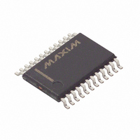
DS1780E+T&R Maxim Integrated Products, DS1780E+T&R Datasheet - Page 16

DS1780E+T&R
Manufacturer Part Number
DS1780E+T&R
Description
IC CPU PERIPHERAL MON 24-TSSOP
Manufacturer
Maxim Integrated Products
Datasheet
1.DS1780E.pdf
(28 pages)
Specifications of DS1780E+T&R
Function
Thermal Monitor, CPU Peripherals
Topology
ADC (Sigma Delta), Comparator, Fan Speed Control, Register Bank
Sensor Type
Internal
Sensing Temperature
-40°C ~ 125°C
Output Type
I²C™/SMBus™
Output Alarm
No
Output Fan
Yes
Voltage - Supply
2.8 V ~ 5.75 V
Operating Temperature
-40°C ~ 125°C
Mounting Type
Surface Mount
Package / Case
24-TSSOP
Lead Free Status / RoHS Status
Lead free / RoHS Compliant
Note: To properly implement the NAND TREE test on the PCB, no pins listed in the tree should be
connected directly to power or ground; if a pin is needed to configure as a permanent low such as an
address, it should be connected to ground through a low value resister such as 330 (to allow the ATE
(Automatic Test Equipment) to drive it high.
DS1780 NAND TREE TEST FLOW Figure 7
DS1780 REGISTERS AND RAM
INTERNAL ADDRESS REGISTER Table 10.0
ADDRESS POINTER (POWER ON DEFAULT 00h) Table 10.1
<7:0>
Temperature Configuration Register
BIT
Chassis Intrusion Clear Register
Interrupt
Interrupt
REGISTERS AND RAM
Serial Address Register
Configuration Register
INT
INT
Address Pointer
VID 4 Register
Analog Output
VID Register
Test Register
Company ID
Value RAM
INT
INT
Mask Register 1
Mask Register 2
NAME
Stepping
Status Register 1
Status Register 2
R/W
W
Address of RAM and Registers. See the tables below for detail.
<A7:A0>
20h-3Dh
(HEX)
4Bh
3Eh
3Fh
40h
41h
42h
43h
44h
46h
47h
48h
49h
15h
19h
16 of 28
POWER ON VALUE OF REGISTERS:
<7:4> = 0101, <3:0> = VID3 - VID0
DESCRIPTION
<7:1> = 1000 000, <0>=VID 4
<7:0> (BINARY)
0000 1000
0000 0000
0000 0000
0000 0000
0000 0000
0000 0000
0010 1101
0000 0001
0000 0000
1111 1111
1101 1010
0000 0001


