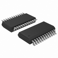
ADT7476AARQZ-REEL ON Semiconductor, ADT7476AARQZ-REEL Datasheet - Page 19

ADT7476AARQZ-REEL
Manufacturer Part Number
ADT7476AARQZ-REEL
Description
IC REMOTE THERMAL CTRLR 24-QSOP
Manufacturer
ON Semiconductor
Series
dBCool®r
Datasheet
1.ADT7476AARQZ.pdf
(67 pages)
Specifications of ADT7476AARQZ-REEL
Function
Fan Control, Temp Monitor
Topology
ADC, Comparator, Fan Speed Counter, Multiplexer, Register Bank
Sensor Type
External & Internal
Sensing Temperature
-40°C ~ 125°C, External Sensor
Output Type
SMBus™
Output Alarm
No
Output Fan
Yes
Voltage - Supply
3 V ~ 3.6 V
Operating Temperature
-40°C ~ 125°C
Mounting Type
Surface Mount
Package / Case
24-QSOP
Lead Free Status / RoHS Status
Lead free / RoHS Compliant
and 0x72) for the Remote 1 and Remote 2 temperature
channels. By doing a one-time calibration of the system, the
user can determine the offset caused by system board noise
and null it out using the offset registers. The offset registers
automatically add a twos complement 8-bit reading to every
temperature measurement.
changes the resolution and therefore, the range of the
temperature offset as either having a −63°C to +127°C range
with a resolution of 1°C or having a −63°C to +64°C range
with a resolution of 0.5°C. This temperature offset can be
used to compensate for linear temperature errors introduced
by noise.
Temperature Offset Registers
Register 0x70, Remote 1 Temperature Offset = 0x00 (0°C
default)
Register 0x71, Local Temperature Offset = 0x00 (0°C default)
Register 0x72, Remote 2 Temperature Offset = 0x00 (0°C
default)
ADT7463/ADT7476A Backwards Compatible Mode
temperature measurements are stored in the zone
temperature reading registers (0x25, 0x26, and 0x27) in
twos complement in the −63°C to +127°C range. The
temperature limits must be reprogrammed in twos
complement.
entered, the temperature is clamped to −63°C. In this mode,
the diode fault condition remains −128°C = 1000 0000,
while in the extended temperature range (−63°C to +191°C),
the fault condition is represented by −64°C = 0000 0000.
Temperature Reading Registers
Register 0x25, Remote 1 Temperature
Register 0x26, Local Temperature
Register 0x27, Remote 2 Temperature
Register 0x77, Extended Resolution 2 = 0x00 default
[7:6] TDM2, Remote 2 temperature LSBs.
[5:4] LTMP, Local temperature LSBs.
[3:2] TDM1, Remote 1 temperature LSBs.
Temperature Limit Registers
are high and low limit registers. Exceeding the programmed
high or low limit causes the appropriate status bit to be set.
Exceeding either limit can also generate SMBALERT
interrupts (depending on the way the interrupt mask register
is programmed and assuming that SMBALERT is set as an
output on the appropriate pin).
The ADT7476A has temperature offset registers (0x70
Changing Bit 1 of Configuration Register 5 (0x7C)
By setting Bit 0 of Configuration Register 5 (0x7C), all
If a twos complement temperature below −63°C is
Associated with each temperature measurement channel
http://onsemi.com
19
Register 0x4E, Remote 1 Temperature Low Limit = 0x81 default
Register 0x4F, Remote 1 Temperature High Limit = 0x7F
default
Register 0x50, Local Temperature Low Limit = 0x81 default
Register 0x51, Local Temperature High Limit = 0x7F default
Register 0x52, Remote 2 Temperature Low Limit = 0x81 default
Register 0x53, Remote 2 Temperature High Limit = 0x7F
default
Reading Temperature from the ADT7476A
the ADT7476A as an 8-bit value (with 1°C resolution) or as
a 10-bit value (with 0.25°C resolution). If only 1°C
resolution is required, the temperature readings can be read
back at any time and in no particular order.
2-register read for each measurement. Extended Resolution
Register 2 (0x77) should be read first. This causes all
temperature reading registers to be frozen until all
temperature reading registers have been read from. This
prevents an MSB reading from being updated while its two
LSBs are being read and vice versa.
Additional ADC Functions for Temperature
Measurement
ADT7476A to offer the system designer increased
flexibility.
Turn-Off Averaging
register, 16 readings have actually been made internally, and
the results averaged, before being placed into the value
register. Sometimes it is necessary to take a very fast
measurement. Setting Bit 4 of Configuration Register 2
(0x73) turns averaging off. The default round robin cycle
time takes 146.5 ms.
default round robin cycle time increases to 240 ms.
Table 8. Conversion Time with Averaging Disabled
Table 9. Conversion Time with Averaging Enabled
Voltage Channels
Remote Temperature 1
Remote Temperature 2
Local Temperature
Voltage Channels
Remote Temperature
Local Temperature
It is important to note that temperature can be read from
If the 10-bit measurement is required, this involves a
A number of other functions are available on the
For each temperature measurement read from a value
When Bit 7 of Configuration Register 6 (0x10) is set, the
Channel
Channel
Measurement Time (ms)
Measurement Time (ms)
39
12
11
0.7
1.3
7
7


