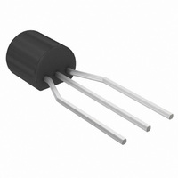
TLV431ALPRPG ON Semiconductor, TLV431ALPRPG Datasheet - Page 3

TLV431ALPRPG
Manufacturer Part Number
TLV431ALPRPG
Description
IC REG SHUNT LV PREC 1.24V TO-92
Manufacturer
ON Semiconductor
Datasheet
1.TLV431ALPG.pdf
(14 pages)
Specifications of TLV431ALPRPG
Reference Type
Shunt, Adjustable
Voltage - Output
1.24 ~ 16 V
Tolerance
±1%
Number Of Channels
1
Current - Cathode
55µA
Current - Output
20mA
Operating Temperature
-40°C ~ 85°C
Mounting Type
Through Hole
Package / Case
TO-92-3 (Standard Body), TO-226
Product
Voltage References
Topology
Shunt References
Output Voltage
Adjustable
Initial Accuracy
1 %
Series Vref - Input Voltage (max)
18 V
Shunt Current (max)
20 mA
Maximum Operating Temperature
+ 85 C
Minimum Operating Temperature
- 40 C
Mounting Style
Through Hole
Shunt Current (min)
0.08 mA
Lead Free Status / RoHS Status
Lead free / RoHS Compliant
Voltage - Input
-
Temperature Coefficient
-
Current - Quiescent
-
Lead Free Status / Rohs Status
Lead free / RoHS Compliant
Other names
TLV431ALPRPG
TLV431ALPRPGOSTR
TLV431ALPRPGOSTR
1. Ambient temperature range: T
2. The deviation parameters DV
3. The dynamic impedance Z
ELECTRICAL CHARACTERISTICS
Reference Voltage (Figure 3)
Reference Input Voltage Deviation Over Temperature (Figure 3)
Ration of Reference Input Voltage Change to Cathode Voltage
Reference Terminal Current (Figure 4)
Reference Input Current Deviation Over Temperature (Figure 4)
Minimum Cathode Current for Regulation (Figure 3)
Off−State Cathode Current (Figure 5)
Dynamic Impedance (Figure 3)
full operating ambient temperature range that applied.
The average temperature coefficient of the reference input voltage, aV
aV
Example: DV
Example:
Example:
When the device is operating with two external resistors, R1 and R2, (refer to Figure 4) the total dynamic impedance of the circuit is given by:
(V
(T
(V
Change (Figure 4)
(V
(I
(I
(V
(V
(V
K
K
ref
A
KA
KA
KA
KA
KA
KA
= 10 mA, R1 = 10 kW, R2 = open)
= 10 mA, R1 = 10 kW, R2 = open, Notes 1, 2)
= T
can be positive or negative depending on whether V
= V
= V
= V
= 6.0 V, V
= 16 V, V
= V
low
ref
ref
ref
ref
V
DT
ref
to T
, I
, I
, I
to 16 V, I
A
ref
K
K
K
@ 25 C = 1.241 V
= 125 C
= 10 mA, T
high
ref
= 10 mA, T
=0.1 mA to 20 mA, f
= 7.2 mV and the slope is positive,
ref
= 0)
= 0)
, Note 1)
K
= 10 mA)
Characteristic
A
A
KA
= T
= 25 C)
ref
is defined as:
low
low
and DI
= *40 C, T
to T
V
V
ref
ref
1.0 kHz, Note 3)
high
ref
(T
Max
Min
V
A
are defined as the difference between the maximum value and minimum value obtained over the
, Note 1)
ref
= 25 C unless otherwise noted)
V
high
ref
T
1
ppm
C
= 85 C.
ppm
C
Z KA
Ambient Temperature
+
http://onsemi.com
+
ref
V
0.0072
+ Z KA
Z
1.241
ref
Min or V
KA
125
(DV
(T
A
3
+
ref
+ 25 C)
DT
ref
DV
Symbol
10
ref
DI
)
I
A
DV
I
Max occurs at the lower ambient temperature, refer to Figure 8.
DV
K(min
|Z
DV
KA
DI
K(off)
V
I
6
K
is defined as:
+ 46 ppm C
ref
KA
ref
1 ) R1
ref
ref
KA
ref
|
)
T
R2
2
10
DV
DT
1.228
1.215
Min
6
−
−
−
−
−
−
−
−
A
ref
= T
= V
TLV431A
2
1.240
0.012
ref
−0.6
0.15
0.04
0.01
0.25
− T
Typ
7.2
55
−
Max − V
1
1.252
1.265
Max
−1.5
0.08
0.04
0.05
0.3
0.4
20
80
ref
Min
1.234
1.228
Min
−
−
−
−
−
−
−
−
TLV431B
1.240
0.012
−0.6
0.15
0.04
0.01
0.25
Typ
7.2
55
−
1.246
1.252
Max
−1.5
0.08
0.04
0.05
0.3
0.4
20
80
Unit
mV
mV
mA
mA
mA
mA
W
V
V


