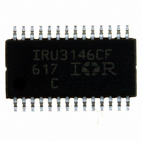
IRU3146CFTR International Rectifier, IRU3146CFTR Datasheet - Page 14

IRU3146CFTR
Manufacturer Part Number
IRU3146CFTR
Description
IC PWM DUAL SYNC 28-TSSOP
Manufacturer
International Rectifier
Specifications of IRU3146CFTR
Pwm Type
Voltage Mode
Number Of Outputs
2
Frequency - Max
345kHz
Duty Cycle
85%
Voltage - Supply
4.5 V ~ 16 V
Buck
Yes
Boost
No
Flyback
No
Inverting
No
Doubler
No
Divider
No
Cuk
No
Isolated
No
Operating Temperature
0°C ~ 70°C
Package / Case
28-TSSOP
Frequency-max
345kHz
Lead Free Status / RoHS Status
Contains lead / RoHS non-compliant
IRU3146
To cancel one of the LC filter poles, place the zero be-
fore the LC filter resonant frequency pole:
Using equations (13) and (15) to calculate C
Same calcuation For V
C
One more capacitor is sometimes added in parallel with
C
used to suppress the switching noise. The additional
pole is given by:
The pole sets to one half of switching frequency which
results in the capacitor C
14
For V
V
V
F
F
C
9
C
8
for F
R
O1
ESR
IN
OSC
F
F
For:
Lo = 1.71µH
Co = 660µF
and R
POLE
= 22nF
9
Where:
V
V
F
F
F
R
g
This results to R
Choose R
Z
Z
4
≅ 17.18nF; Choose C
= 12V
= 30KHz
m
≅ 0.75×
=
IN
OSC
O1
ESR
LC
≅ 75%F
5
= 12KHz
= 1.25V
P
2.5V
and R
= Error Amplifier Transconductance
=
= Maximum Input Voltage
V
= Crossover Frequency
= Resonant Frequency of the Output Filter
<<
V
4
= Zero Frequency of the Output Capacitor
OSC
= Oscillator Ramp Voltage
:
. This introduces one more pole which is mainly
π×R
IN
f
2
×
F
S
6
LC
P
4
= Resistor Dividers for Output Voltage
2π
=2.61K
4
F
=
×f
Programming
O1
1
2π×R
F
×F
S
LC
-
L
4
1
2
=2.61K
O
ESR
C
1
× C
1.8V
9
4
×
POLE:
×
9
≅
will result to: R
1
F
R
R
g
=18nF
R
O
C
C
m
LC
5
6
F
R
π×R
5
9
9
R
= 1K
= 2.14K
= 2000µmho
Z
+ R
4
×C
= 4.75KHz
+ C
5
= 3.56KHz
= 2.61K
1
6
4
POLE
POLE
×f
×
---(15)
S
g
1
m
3
= 2.8K and
9
, we get:
---(14)
www.irf.com
For a general solution for unconditional stability for ce-
ramic output capacitor with very low ESR or any type of
output capacitors, in a wide range of ESR values we
should implement local feedback with a compensation
network. The typically used compensation network for a
voltage-mode controller is shown in Figure 16.
In such configuration, the transfer function is given by:
The error amplifier gain is independent of the transcon-
ductance under the following condition:
By replacing Z
former function can be expressed as:
H(s) =
As known, transconductance amplifier has high imped-
ance (current source) output, therefore, consider should
be taken when loading the E/A output. It may exceed its
source/sink output current capability, so that the ampli-
fier will not be able to swing its output voltage over the
necessary range.
The compensation network has three poles and two ze-
ros and they are expressed as follows:
H(s) dB
g
m
V
Z
Figure 16- Compensation network with local
V
Z
OUT
f
sR
IN
e
>> 1
Gain(dB)
feedback and its asymptotic gain plot.
6
R
=
(C
C
8
10
1
12
1 + g
F
1 - g
+C
IN
V
Z
and
1
OUT
and Z
11
m
m
R
R
)
Z
Z
×
6
5
IN
f
F
[
f
Vp=V
Z
g
according to Figure 16, the trans-
1+sR
(1+sR
2
Fb
m
Z
IN
REF
>>1
7
(
7
C
R
C
C
11
7
F
E/A
12
P
)×[1+sC
12
+C
2
C
11
C
11
)]
12
F
×(1+sR
---(16)
C
P
10
Comp
3
11
(R
Frequency
6
+R
Rev. 1.1
Z
8
6/25/04
8
Ve
f
C
)]
10
)


