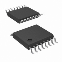
LM5025MTC/NOPB National Semiconductor, LM5025MTC/NOPB Datasheet

LM5025MTC/NOPB
Specifications of LM5025MTC/NOPB
*LM5025MTC/NOPB
LM5025MTC
Available stocks
Related parts for LM5025MTC/NOPB
LM5025MTC/NOPB Summary of contents
Page 1
... UP/DOWN sync capability, pre- cision reference and thermal shutdown. Typical Application Circuit Simplified Active Clamp Forward Power Converter © 2004 National Semiconductor Corporation Features n Internal Start-up Bias Regulator n 3A Compound Main Gate Driver n Programmable Line Under-Voltage Lockout (UVLO) with ...
Page 2
Connection Diagram Ordering Information Order Number Package Type LM5025MTC TSSOP-16 LM5025MTCX TSSOP-16 LM5025SD LLP-16 LM5025SDX LLP-16 Pin Description PIN NAME 1 V Source Input Voltage IN 2 RAMP Modulator ramp signal 3 CS1 Current sense input for cycle-by-cycle limiting If ...
Page 3
Pin Description (Continued) PIN NAME 7 V Output from the internal high voltage start-up CC regulator. The V 7.6V. 8 OUT_A Main output driver 9 OUT_B Active Clamp output driver 10 PGND Power ground 11 AGND Analog ground 12 SS ...
Page 4
Block Diagram www.national.com Simplified Block Diagram 4 20086902 ...
Page 5
... Absolute Maximum Ratings If Military/Aerospace specified devices are required, please contact the National Semiconductor Sales Office/ Distributors for availability and specifications GND GND CC CS1, CS2 to GND All other inputs to GND ESD Rating (Note 2) Human Body Model Electrical Characteristics Specifications with standard typeface are for T Temperature range ...
Page 6
Electrical Characteristics Specifications with standard typeface are for T Temperature range 48V Symbol Parameter Soft-Start Soft-start Current Source Normal Soft-start Current Source following a CS2 event Oscillator Frequency1 Frequency2 Sync threshold Min Sync Pulse Width ...
Page 7
... Note 1: Absolute Maximum Ratings are limits beyond which damage to the device may occur. Operating Ratings are conditions under which operation of the device is intended to be functional. For guaranteed specifications and test conditions, see the Electrical Characteristics. Note 2: For detailed information on soldering plastic TSSOP and LLP packages, refer to the Packaging Data Book available from National Semiconductor Corporation. ...
Page 8
Typical Performance Characteristics V Regulator Start-up Characteristics REF REF Overlap Time vs R www.national.com vs Vin CC 20086903 20086905 SET 20086907 20086904 Oscillator Frequency vs RT 20086906 Overlap Time ...
Page 9
Typical Performance Characteristics Dead Time vs R SET SS Pin Current vs Temperature (Continued) Dead Time vs Temperature 20086909 20086911 29.5K SET 20086910 www.national.com ...
Page 10
Detailed Operating Description The LM5025 PWM controller contains all of the features necessary to implement power converters utilizing the Active Clamp Reset technique. The device can be configured to control either a P-Channel clamp switch or an N-Channel clamp switch. ...
Page 11
PWM Outputs (Continued) Compound Gate Drivers The LM5025 contains two unique compound gate drivers, which parallel both MOS and Bipolar devices to provide high drive current throughout the entire switching event. The Bi- polar device provides most of the drive ...
Page 12
Current Limit (Continued) the PWM comparator will produce the first output pulse at OUT_A. After the first pulse occurs, the softstart current source will revert to the normal 20µA level. Fully discharging and then slowly charging the SS capacitor protects ...
Page 13
Soft-start The softstart feature allows the power converter to gradually reach the initial steady state operating point, thus reducing start-up stresses and surges. At power on, a 20µA current is sourced out of the softstart pin (SS) into an external ...
Page 14
www.national.com 14 ...
Page 15
Physical Dimensions inches (millimeters) unless otherwise noted Note recommended that the exposed pad be connected to Pin 11 (AGND) Molded TSSOP-16 NS Package Number MTC16 16-Lead LLP Surface Mount Package NS Package Number SDA16A 15 www.national.com ...
Page 16
... BANNED SUBSTANCE COMPLIANCE National Semiconductor certifies that the products and packing materials meet the provisions of the Customer Products Stewardship Specification (CSP-9-111C2) and the Banned Substances and Materials of Interest Specification (CSP-9-111S2) and contain no ‘‘Banned Substances’’ as defined in CSP-9-111S2. ...


