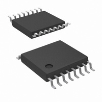
LM25115MT/NOPB National Semiconductor, LM25115MT/NOPB Datasheet - Page 2

LM25115MT/NOPB
Manufacturer Part Number
LM25115MT/NOPB
Description
IC CTRLR SSPR 42V LD REG 16TSSOP
Manufacturer
National Semiconductor
Datasheet
1.LM25115SDNOPB.pdf
(17 pages)
Specifications of LM25115MT/NOPB
Pwm Type
Voltage/Current Mode
Number Of Outputs
2
Frequency - Max
1MHz
Duty Cycle
90%
Voltage - Supply
5 V ~ 7.5 V
Buck
Yes
Boost
No
Flyback
No
Inverting
No
Doubler
No
Divider
No
Cuk
No
Isolated
No
Operating Temperature
-40°C ~ 125°C
Package / Case
16-TSSOP
Frequency-max
1MHz
Lead Free Status / RoHS Status
Lead free / RoHS Compliant
Other names
*LM25115MT
*LM25115MT/NOPB
LM25115MT
*LM25115MT/NOPB
LM25115MT
www.national.com
LM25115MT
LM25115MTX
LM25115SD
LM25115SDX
Pin
Connection Diagram
Ordering Information
Pin Descriptions
1
2
3
4
5
6
7
8
Ordering Number
COMP
AGND
RAMP
Name
VOUT
CS
CO
FB
SS
Current Sense amplifier positive input
Current sense amplifier negative input
Analog ground
Current limit output
Compensation. Error amplifier output
Feedback. Error amplifier inverting input
Soft-start control
PWM Ramp signal
Package Type
TSSOP-16
TSSOP-16
Description
LLP-16
LLP-16
See NS Package Numbers MTC16 and SDA16A
16-Lead TSSOP, LLP
NSC Package Drawing
2
A low inductance current sense resistor is connected between
CS and VOUT. Current limiting occurs when the differential
voltage between CS and VOUT exceeds 45mV (typical).
Connected directly to the output voltage. The current sense
amplifier operates over a voltage range from 0V to 13.5V at the
VOUT pin.
Connect directly to the power ground pin (PGND).
For normal current limit operation, connect the CO pin to the
COMP pin. Leave this pin open to disable the current limit
function.
COMP pin pull-up is provided by an internal 300uA current
source.
Connected to the regulated output through the feedback resistor
divider and compensation components. The non-inverting input
of the error amplifier is internally connected to the SS pin.
An external capacitor and the equivalent impedance of an
internal resistor divider connected to the bandgap voltage
reference set the soft-start time. The steady state operating
voltage of the SS pin equal to 0.75V (typical).
An external capacitor connected to this pin sets the ramp slope
for the voltage mode PWM. The RAMP capacitor is charged
with a current that is proportional to current into the SYNC pin.
The capacitor is discharged at the end of every cycle by an
internal MOSFET.
SDA16A
SDA16A
MTC16
MTC16
20172602
Application Information
2500 shipped as Tape & Reel
92 Units Per Anti-Static Tube
Available Soon
Available Soon
Supplied As


