MIC22602YML TR Micrel Inc, MIC22602YML TR Datasheet - Page 11
MIC22602YML TR
Manufacturer Part Number
MIC22602YML TR
Description
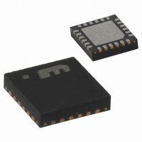
ID BUCK SYNC ADJ 6A 24MLF
Manufacturer
Micrel Inc
Type
Step-Down (Buck), PWM - Voltage Moder
Datasheet
1.MIC22602YML_TR.pdf
(24 pages)
Specifications of MIC22602YML TR
Internal Switch(s)
Yes
Synchronous Rectifier
Yes
Number Of Outputs
1
Voltage - Output
Adj to 0.7V
Current - Output
6A
Frequency - Switching
1MHz
Voltage - Input
2.6 ~ 5.5 V
Operating Temperature
-40°C ~ 125°C
Mounting Type
Surface Mount
Package / Case
24-MLF®, QFN
Voltage - Supply
2.6 V ~ 5.5 V
Frequency-max
1.2MHz
Duty Cycle
100%
Pwm Type
Voltage Mode
Buck
Yes
Boost
No
Flyback
No
Inverting
No
Doubler
No
Divider
No
Cuk
No
Isolated
No
Lead Free Status / RoHS Status
Lead free / RoHS Compliant
Other names
576-3645-2
MIC22602YML TR
MIC22602YMLTR
MIC22602YML TR
MIC22602YMLTR


Application Information
The MIC22602 is a 6A Synchronous step down regulator
IC with a fixed 1 MHz, voltage mode PWM control
scheme. The other features include tracking and
sequencing control for controlling multiple output power
systems, power on reset.
Component Selection
Input Capacitor
A minimum 22µF ceramic is recommended on each of
the PVIN pins for bypassing. X5R or X7R dielectrics are
recommended for the input capacitor. Y5V dielectric is
not recommended.
Output Capacitor
The MIC22602 was designed specifically for the use of
ceramic output capacitors. Additional 100µF can improve
transient performance. Since the MIC22602 is in voltage
mode, the control loop relies on the inductor and output
capacitor for compensation. For this reason, do not use
excessively large output capacitors. The output capacitor
requires either an X7R or X5R dielectric. Y5V and Z5U
dielectric capacitors, aside from the undesirable effect of
their wide variation in capacitance over temperature,
become resistive at high frequencies. Using Y5V or Z5U
capacitors can cause instability in the MIC22602.
Inductor Selection
Inductor selection is determined by the following (not
necessarily in the order of importance):
The MIC22602 is designed to use a 0.47µH to 4.7µH
inductor.
Maximum current ratings of the inductor are generally
given in two methods: permissible DC current and
saturation current. Permissible DC current can be rated
either for a 40°C temperature rise or a 10% loss in
inductance. Ensure the inductor selected can handle the
maximum operating current. When saturation current is
specified, make sure that there is enough margin that
the peak current will not saturate the inductor. The ripple
can add as much as 1.2A to the output current level. The
RMS rating should be chosen to be equal or greater than
the current limit of the MIC22602 to prevent overheating
in a fault condition. For best electrical performance, the
inductor should be placed very close to the SW nodes of
the IC. It is important to test all operating limits before
settling on the final inductor choice.
Micrel, Inc.
October 2009
•
•
•
•
Inductance
Rated current value
Size requirements
DC resistance (DCR)
11
The size requirements refer to the area and height
requirements that are necessary to fit a particular
design. Please refer to the inductor dimensions on their
datasheet.
DCR is inversely proportional to size and represents
efficiency loss. Refer to the “Efficiency Considerations”
below for a more detailed description.
EN/DLY Capacitor
EN/DLY sources 1µA out of the IC to allow a startup
delay to be implemented. The delay time is simply the
time it takes 1µA to charge C
Efficiency Considerations
Efficiency is defined as the amount of useful output
power, divided by the amount of power consumed.
Maintaining high efficiency serves two purposes. It
decreases power dissipation in the power supply,
reducing the need for heat sinks and thermal design
considerations and it decreases consumption of current
for battery powered applications. Reduced current drawn
from a battery increases the devices operating time,
particularly critical in hand held devices.
There are mainly two loss terms in switching converters:
conduction losses and switching losses. Conduction loss
is simply the power losses due to VI or I
power is dissipated in the high side switch during the on
cycle. The power loss is equal to the high side MOSFET
RDS
(I
MOSFET conducts, also dissipating power. Similarly, the
inductor’s DCR and capacitor’s ESR also contribute to
the I
efficiency by the product of the quiescent (operating)
current and the supply voltage. The power consumed for
switching at 1MHz frequency and power loss due to
switching transitions add up to switching losses.
SW
2
). During the off cycle, the low side N-Channel
ON
2
R losses. Device operating current also reduces
Efficiency % =
multiplied by the RMS Switch Current squared
T
DLY
=
. 1
1
24
×
10
⋅
C
−
⎛
⎜ ⎜
⎝
DLY
6
V
OUT
V
IN
DLY
×
×
I
I
to 1.25V. Therefore:
OUT
IN
⎞
⎟ ⎟
⎠
×
100
2
M9999-102809-A
R. For example,
MIC22602
Related parts for MIC22602YML TR
Image
Part Number
Description
Manufacturer
Datasheet
Request
R

Part Number:
Description:
Manufacturer:
Micrel Inc
Datasheet:
Part Number:
Description:
Manufacturer:
Micrel Inc
Datasheet:
Part Number:
Description:
Manufacturer:
Micrel Inc
Datasheet:
Part Number:
Description:
Manufacturer:
Micrel Inc
Datasheet:
Part Number:
Description:
Manufacturer:
Micrel Inc
Datasheet:
Part Number:
Description:
Manufacturer:
Micrel Inc
Datasheet:
Part Number:
Description:
Manufacturer:
Micrel Inc
Datasheet:
Part Number:
Description:
Manufacturer:
Micrel Inc
Datasheet:
Part Number:
Description:
Manufacturer:
Micrel Inc
Datasheet:
Part Number:
Description:
Manufacturer:
Micrel Inc
Datasheet:
Part Number:
Description:
Manufacturer:
Micrel Inc
Datasheet:
Part Number:
Description:
Manufacturer:
Micrel Inc
Datasheet:
Part Number:
Description:
Manufacturer:
Micrel Inc
Datasheet:
Part Number:
Description:
Manufacturer:
Micrel Inc
Datasheet: