C1632C103K5RACTU Kemet, C1632C103K5RACTU Datasheet - Page 3
C1632C103K5RACTU
Manufacturer Part Number
C1632C103K5RACTU
Description
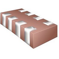
CAP 4-ARRAY 10000PF 50V X7R 1632
Manufacturer
Kemet
Type
Ceramicr
Specifications of C1632C103K5RACTU
Capacitance
10000pF
Voltage - Rated
50V
Dielectric Material
Ceramic
Number Of Capacitors
4
Circuit Type
Isolated
Temperature Coefficient
X7R
Tolerance
±10%
Mounting Type
Surface Mount
Package / Case
0612 (1632 Metric)
Height
0.053" (1.35mm)
Size / Dimension
0.126" L x 0.063" W (3.20mm x 1.60mm)
No. Of Capacitors
4
Tolerance (+ Or -)
10%
Voltage
50VDC
Number Of Terminals
8Terminal
Temp Coeff (dielectric)
X7R
Operating Temp Range
-55C to 125C
Mounting Style
Surface Mount
Construction
SMT Chip
Failure Rate
Not Required
Product Height (mm)
1.35mm
Product Depth (mm)
1.6mm
Product Length (mm)
3.2mm
Lead Diameter (nom)
Not Requiredmm
Terminal Pitch
0.8mm
Capacitance Tolerance
± 10%
Voltage Rating
50V
Capacitor Case Style
0612
Operating Temperature Range
-55°C To +125°C
Capacitor Mounting
SMD
Rohs Compliant
Yes
Lead Free Status / RoHS Status
Lead free / RoHS Compliant
Other names
C1632C103K5RAC
C1632C103K5RAC7800
C1632C103K5RAC7800


© KEMET Electronics Corporation • P.O. Box 5928 • Greenville, SC 29606 (864) 963-6300 • www.kemet.com
Surface Mount Multilayer Ceramic Chip Capacitors (SMD MLCCs) – X7R Dielectric, 6.3VDC–250VDC (Commercial Grade)
Electrical Parameters/Characteristics
Regarding Aging Rate: Capacitance measurements (including tolerance) are indexed to a referee time of 48 or 1000 Hours. Please refer to a part number specific
datasheet for referee time details.
To obtain IR limit, divide MΩ-µF value by the capacitance and compare to GΩ limit. Select the lower of the two limits.
Capacitance and Dissipation Factor (DF) measured under the following conditions:
Note: When measuring capacitance it is important to ensure the set voltage level is held constant. The HP4284 & Agilent E4980 have a feature known as Automatic
Level Control (ALC). The ALC feature should be switched to "ON".
Post Environmental Limits
Insulation Resistance Limit Table
Capacitance Change with Reference to +25°C and 0 Vdc Applied (TCC)
1kHz ± 50Hz and 1.0 ± 0.2 Vrms if capacitance ≤10µF
120Hz ± 10Hz and 0.5 ± 0.1 Vrms if capacitance >10µF
Dielectric
EIA Case Size
X7R
0201
0402
0603
0805
1206
1808
2220
2225
1210
1812
1825
Rated DC Voltage
Dissipation Factor (DF) Maximum Limits @ 25ºC
High Temperature Life, Biased Humidity, Moisture Resistance
16 / 25
Aging Rate (Max % Cap Loss/Decade Hour)
< 16
>25
Insulation Resistance (IR) Limit @ 25°C
Item
1000 megohm microfarads
Dielectric Withstanding Voltage
Operating Temperature Range
Capacitance Value
or 100GΩ
< 0.22µF
< 0.39µF
< .012µF
< .047µF
< .047µF
< 2.2µF
< 10µF
ALL
ALL
ALL
N/A
All
DF (%)
3.0
5.0
7.5
-55°C to +125°C
±15%
3.0%
250% of rated voltage
(5 ± 1 seconds and charge/discharge not exceeding 50mA)
5%(10V), 3.5%(16V & 25V) and 2.5%(50V to 250V)
See Insulation Resistance Limit Table
(Rated voltage applied for 120 ± 5 secs @ 25°C)
500 megohm microfarads
or 10GΩ
≥ .012µF
≥ .047µF
≥ .047µF
≥ 0.22µF
≥ 0.39µF
≥ 2.2µF
≥ 10µF
ALL
N/A
N/A
N/A
Cap Shift
± 20%
Parameters/Characteristics
10% of Initial Limit
IR
C1002_X7R • 6/15/2011
3
Related parts for C1632C103K5RACTU
Image
Part Number
Description
Manufacturer
Datasheet
Request
R

Part Number:
Description:
CAP, KEMET #F601BL105K250C
Manufacturer:
Kemet
Datasheet:
Part Number:
Description:
Manufacturer:
Kemet
Datasheet:
Part Number:
Description:
Manufacturer:
Kemet
Datasheet: