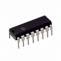
TC170CPE Microchip Technology, TC170CPE Datasheet

TC170CPE
Specifications of TC170CPE
Available stocks
Related parts for TC170CPE
TC170CPE Summary of contents
Page 1
... I LIM V OUT 2 REF – SENSE + SENSE TC170CPE + ERROR AMP IN 5 – ERROR AMP IN 6 CMPTR NOTE: Outputs LOW in "OFF" state. 2002 Microchip Technology Inc. © General Description The TC170 offers maximum supply current of 3.8mA. Bipolar current-mode control integrated circuits require five times more operating current ...
Page 2
... NOTE: Outputs low in OFF state. DS21395B-page 2 V REF 2 5.1-Volt Reference Undervoltage Lockout PWM Q R Comparator PWM Latch + – Q4 Shutdown Comparator – Positive Feedback 3.5kΩ TC170 Output Output Ground 1 Current Limit/ Soft-Start Adjust 16 + Shutdown 350 – mV 6kΩ 2002 Microchip Technology Inc. © ...
Page 3
... Minimum Latching Current at Pin Maximum Nonlatching Current at Pin 1 L 2002 Microchip Technology Inc. © *Stresses above those listed under "Absolute Maximum Ratings" may cause permanent damage to the device. These are stress ratings only and functional operation of the device at these or any other conditions above those indicated in the operation sections of the specifications is not implied ...
Page 4
... O A Min Typ Max V – – – 150 50 150 7.15 7.7 8.25 0.5 0.75 1 2.7 3.8 Units Test Conditions V Pin 20mA SINK 100mA SINK 20mA SOURCE 100mA SOURCE nsec C = 1000pF L nsec C = 1000pF L V Threshold V mA 2002 Microchip Technology Inc. © ...
Page 5
... Voltage bias supply for all TC170 circuits except the output transistors SHDN Input pin to disable both output drives to 0V OFF. 2002 Microchip Technology Inc. © Description ) input to set oscillator frequency in conjunction with pin input to set oscillator frequency by setting constant current charge rate to O ...
Page 6
... Typical time delay values are in the 300 to 400nsec region at 25°C. The delay time increases with device temperature so that at 50°C, the delay times may be increased by as much as 100nsec. 2002 Microchip Technology Inc. © – PIN4 ...
Page 7
... Error Amplifier – Q3 350mV TC170 FIGURE 3-2: GROUND REFERENCE RESISTIVE SENSING x 3.15 Current Sense Amplifier – 3 TC170 *Optional RC Filter 2002 Microchip Technology Inc. © PWM Comparator + – From Undervoltage Lockout Q4 + – Limit Buffer Amplifier Lock-Up Amplifier – Positive Feedback 3.5kΩ ...
Page 8
... DS21395B-page 8 FIGURE 3- FIGURE 3-6: External* Oscillator *Pulse Width of Oscillator MASTER/SLAVE PARALLEL OPERATION TC170 8 C SYNC CMPTR Master 1/2 TC4427 SYNC CMPTR REF TC170 Slave EXTERNAL CLOCK SYNCHRONIZATION 1 TC4427 8 10 TC170 C SYNC REF TC170 C SYNC REF 2002 Microchip Technology Inc. © ...
Page 9
... Dead time is approximately: 2000 [ 2.3 1 – where Oscillator Resistor (kΩ Oscillator Capacitor (pF Output Dead Time (sec) D Maximum possible duty cycle is set by the dead time. 2002 Microchip Technology Inc. © Pin 8 + 2.3V 2. – Pin FIGURE 3- – ...
Page 10
... LOAD V = 16V S 5V DIV 50 nsec DIV DS21395B-page 10 Output Rise and Fall Times T = +25° 1800pF LOAD V = 16V S 5V DIV 5 nsec DIV Output Rise and Fall Times T = +25° 1000pF LOAD V = 16V S 5V DIV 50 nsec DIV 2002 Microchip Technology Inc. © ...
Page 11
... Taping Form Component Taping Orientation for 16-Pin SOIC (Wide) Devices PIN 1 Carrier Tape, Number of Components Per Reel and Reel Size Package 16-Pin SOIC (W) 2002 Microchip Technology Inc. © User Direction of Feed P Standard Reel Component Orientation for TR Suffix Device Carrier Width (W) ...
Page 12
... MAX. .012 (0.30) .004 (0.10) .050 (1.27) .016 (0.40) .310 (7.87) .290 (7.37) 10° MAX. .400 (10.16) .310 (7.87) Dimensions: inches (mm) .013 (0.33) .009 (0.23) Dimensions: inches (mm) 2002 Microchip Technology Inc. © ...
Page 13
... The Microchip Worldwide Site (www.microchip.com) Please specify which device, revision of silicon and Data Sheet (include Literature #) you are using. New Customer Notification System Register on our web site (www.microchip.com/cn) to receive the most current information on our products. 2002 Microchip Technology Inc. TC170 DS21395B-page13 ...
Page 14
... TC170 NOTES: DS21395B-page14 2002 Microchip Technology Inc. ...
Page 15
... Serialized Quick Turn Programming (SQTP service mark of Microchip Technology Incorporated in the U.S.A. All other trademarks mentioned herein are property of their respective companies. © 2002, Microchip Technology Incorporated, Printed in the U.S.A., All Rights Reserved. Printed on recycled paper. Microchip received QS-9000 quality system ...
Page 16
... Korea Microchip Technology Korea 168-1, Youngbo Bldg. 3 Floor Samsung-Dong, Kangnam-Ku Seoul, Korea 135-882 Tel: 82-2-554-7200 Fax: 82-2-558-5934 Singapore Microchip Technology Singapore Pte Ltd. 200 Middle Road #07-02 Prime Centre Singapore, 188980 Tel: 65-6334-8870 Fax: 65-6334-8850 Taiwan Microchip Technology Taiwan 11F-3, No. 207 ...


