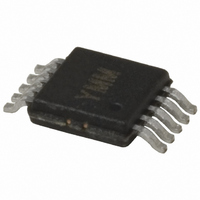
MIC2169BMM TR Micrel Inc, MIC2169BMM TR Datasheet - Page 9

MIC2169BMM TR
Manufacturer Part Number
MIC2169BMM TR
Description
IC CTRLR PWM SYNC BUCK 10-MSOP
Manufacturer
Micrel Inc
Datasheet
1.MIC2169YMM.pdf
(15 pages)
Specifications of MIC2169BMM TR
Pwm Type
Voltage Mode
Number Of Outputs
1
Frequency - Max
550kHz
Duty Cycle
92%
Voltage - Supply
3 V ~ 14.5 V
Buck
Yes
Boost
No
Flyback
No
Inverting
No
Doubler
No
Divider
No
Cuk
No
Isolated
No
Operating Temperature
-40°C ~ 85°C
Package / Case
10-MSOP, Micro10™, 10-uMAX, 10-uSOP
Frequency-max
550kHz
Lead Free Status / RoHS Status
Contains lead / RoHS non-compliant
Other names
MIC2169BMMTR
MIC2169BMMTR
MIC2169BMMTR
The RMS inductor current is used to calculate the I
losses in the inductor.
Maximizing effi ciency requires the proper selection of core
material and minimizing the winding resistance. The high
frequency operation of the MIC2169 requires the use of fer-
rite materials for all but the most cost sensitive applications.
Lower cost iron powder cores may be used but the increase
in core loss will reduce the effi ciency of the power supply.
This is especially noticeable at low output power. The winding
resistance decreases effi ciency at the higher output current
levels. The winding resistance must be minimized although
this usually comes at the expense of a larger inductor. The
power dissipated in the inductor is equal to the sum of the
core and copper losses. At higher output loads, the core
losses are usually insignifi cant and can be ignored. At lower
output currents, the core losses can be a signifi cant con-
tributor. Core loss information is usually available from the
magnetics vendor. Copper loss in the inductor is calculated
by the equation below:
The resistance of the copper wire, R
temperature. The value of the winding resistance used should
be at the operating temperature:
where:
R
ally specifi ed by the manufacturer)
Output Capacitor Selection
The output capacitor values are usually determined capacitors
ESR (equivalent series resistance). Voltage and RMS current
capability are two other important factors to consider when
selecting the output capacitor. Recommended capacitors are
tantalum, low-ESR aluminum electrolytics, and POSCAPS.
The output capacitor’s ESR is usually the main cause of
output ripple. The output capacitor ESR also affects the
overall voltage feedback loop from stability point of view. See:
“Feedback Loop Compensation” section for more information.
The maximum value of ESR is calculated:
where:
March 2009
R
WINDING(20°C)
WINDING(hot)
T
T
V
HOT
20°C
OUT
I
I
P
PK
INDUCTOR(rms)
INDUCTORCu
R
=
= temperature of the wire under operating load
= peak-to-peak output voltage ripple
= ambient temperature
ESR
I
OUT
=
is room temperature winding resistance (usu-
R
(
≤
max
WINDING(20 C)
Δ
=
V
I
PP
=
I
OUT
)
OUT
I
+
INDUCTOR(rms)
0.5 I
(
max
°
×
× +
)
PP
(
×
1 0.0042 (T
1
WINDING
+
2
×
3
1
R
⎛
⎜
⎝
×
I
WINDING
OUT
, increases with
HOT
(
I
P
max
−
T
)
20 C
⎞
⎟
⎠
°
2
2
)
× R
)
9
subjected to high inrush currents, caused by turning the input
supply on. To maximize reliability, tantalum input capacitor
voltage rating should be at least two times the maximum in-
put voltage. Aluminum electrolytic, OS-CON, and multilayer
polymer fi lm capacitors can handle the higher inrush currents
without voltage derating. The input voltage ripple will primar-
ily depends upon the input capacitor’s ESR. The peak input
current is equal to the peak inductor current, so:
The total output ripple is a combination of the ESR output
capacitance. The total ripple is calculated below:
where:
The voltage rating of capacitor should be twice the voltage for
a tantalum and 20% greater for an aluminum electrolytic.
The output capacitor RMS current is calculated below:
The power dissipated in the output capacitor is:
Input Capacitor Selection
The input capacitor should be selected for ripple current rating
and voltage rating. Tantalum input capacitors may fail when
The input capacitor must be rated for the input current ripple.
The RMS value of input capacitor current is determined at
the maximum output current. Assuming the peak-to-peak
inductor ripple current is low:
The power dissipated in the input capacitor is:
Voltage Setting Components
The MIC2169 requires two resistors to set the output voltage
as shown in Figure 2.
I
D = duty cycle
C
f
ΔV
ΔV
PP
S
OUT
I
P
I
P
C
C (rms)
= switching frequency
DISS(C
DISS(C )
IN
OUT
IN
OUT(rms)
= peak-to-peak inductor ripple current
=
= output capacitance value
I
INDUCTOR(peak)
=
≈
IN
OUT
I
OUT
=
⎛
⎜
⎝
=
)
I
PP
I
C
PP
=
(
I
12
C (rms)
max
OUT
I
IN
C
×
OUT(rms) 2
(1 D)
)
×
−
×
f
2
S
×
×
⎞
⎟ +
⎠
D (1 D)
R
R
×
2
ESR(C )
ESR(C )
×
R
(
ESR(C
I
PP
−
IN
IN
×
R
OUT
ESR
)
)
2
M9999-032409


