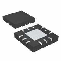
MAX1932ETC+ Maxim Integrated Products, MAX1932ETC+ Datasheet - Page 9

MAX1932ETC+
Manufacturer Part Number
MAX1932ETC+
Description
IC SUPPLY BIAS APD 12-TQFN
Manufacturer
Maxim Integrated Products
Datasheet
1.MAX1932ETC.pdf
(16 pages)
Specifications of MAX1932ETC+
Applications
Controller, Fiber Optic Network
Voltage - Input
2.7 ~ 5.5 V
Number Of Outputs
1
Voltage - Output
4.5 ~ 90 V
Operating Temperature
0°C ~ 85°C
Mounting Type
Surface Mount
Package / Case
12-TQFN Exposed Pad
Lead Free Status / RoHS Status
Lead free / RoHS Compliant
Table 1. Compensation Components for Typical Circuits (Figure 2)
ware by the system through the on-chip DAC, but can
also be accomplished in hardware using an external
thermistor or IC temperature sensor. Figure 8 shows
how an NTC thermistor can be connected to make the
bias voltage increase with temperature.
Careful PC board layout is important for minimizing
ground bounce and noise. In addition, keep all connec-
tions to FB as a short as possible. In particular, locate
feedback resistors (R5, R6, and R8) as close to FB as
possible. Use wide, short traces to interconnect large
current paths for N1, D1, L1, C1, C2. Do not share
these connections with other signal paths. Refer to the
MAX1932 EV kit for a PC board layout example.
V
5V
5V
5V
3V
3V
IN
IN
IN
IN
IN
IN
, V
, 40-90V
, 20-60V
, 20-60V
, 40-90V
, 4.5-15V
OUT
, I
OUT(MAX)
OUT
OUT
OUT
OUT
OUT
PC Board Layout and Grounding
at 2.5mA
at 2.5mA
at 5mA
at 2.5mA
at 2.5mA
_______________________________________________________________________________________
INDUCTOR L1
Digitally Controlled, 0.5% Accurate,
(µH)
100
150
220
82
33
C2 (µF)
C
0.047
0.047
0.10
0.22
0.47
SNS
Safest APD Bias Supply
TRANSISTOR COUNT: 1592
PROCESS: BICMOS
R1 (Ω)
R
806
806
392
806
806
SNS
C3 (µF)
C
0.047
0.10
0.01
0.1
0.1
OUT
Chip Information
R7 (kΩ)
R
COMP
7.5
20
15
10
20
C
C4 (µF)
0.22
0.22
0.47
0.22
0.47
COMP
9


