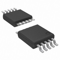
AP6714M10G-13 Diodes Inc, AP6714M10G-13 Datasheet - Page 4

AP6714M10G-13
Manufacturer Part Number
AP6714M10G-13
Description
IC BOOST CONV SYNC 1.8MHZ 10MSOP
Manufacturer
Diodes Inc
Type
Step-Up (Boost)r
Datasheet
1.AP6714M10G-13.pdf
(15 pages)
Specifications of AP6714M10G-13
Internal Switch(s)
Yes
Synchronous Rectifier
Yes
Number Of Outputs
1
Voltage - Output
1.8 ~ 5.5 V
Frequency - Switching
1.8MHz
Voltage - Input
0.9 ~ 5.5 V
Operating Temperature
-40°C ~ 85°C
Mounting Type
Surface Mount
Package / Case
10-MSOP, Micro10™, 10-uMAX, 10-uSOP
Lead Free Status / RoHS Status
Lead free / RoHS Compliant
Current - Output
-
Power - Output
-
Lead Free Status / Rohs Status
Lead free / RoHS Compliant
Other names
AP6714M10GDITR
Available stocks
Company
Part Number
Manufacturer
Quantity
Price
Electrical Characteristics
GENERAL
REFERENCE
OSCILLATOR
STEP-UP DC-TO-DC
THERMAL-SHUTDOWN PROTECTION
LOGIC INPUTS
OVER CURRENT PROTECTION
THERMAL RESISTANCE
AP6714 Rev. 4
Notes:
ΔV
ΔV
V
Symbol
V
R
REF(LOAD)
REF(LINE)
Duty
V
V
F
OUT
I
I
REF
I
DS(ON)
θ
θ
I
I
OUT
STB
LXL
OSC
OCP
CC
REF
LM
JA
JC
/ΔT Tempco of Reference
/ΔT Tempco of Output Voltage
4. The step-up current limit in startup refers to the LX switch current limit, not the output current limit.
5. Test condition for MSOP-10L: Device mounted on 2oz copper, minimum recommended pad layout on top & bottom layer with thermal vias,
double sided FR-4 PCB.
Thermal Resistance
Standby Current
Supply Current
Reference Output Voltage
Reference Load Regulation
Reference Line Regulation
OSC Frequency
FB Input Leakage Current
Step-Up Maximum Duty Cycle FB = 0V
OUT Leakage Current
LX Leakage Current
Switch On-Resistance
N-Channel Current Limit
Thermal Shutdown
Thermal Hysteresis
EN Input Low Level
EN Input High Level
Over Current Protection
Voltage
Thermal Resistance
Junction-to-Ambient
Junction-to-Case
Parameter
(V
www.diodes.com
V
V
-40
10mA < I
2.8 < V
I
FB = 1.25V
V
V
N channel, Vcc= 5V
P channel, Vcc= 5V
V
1.5V < V
1.5V < V
R
MSOP-10L (Note 5)
MSOP-10L (Note 5)
CC
OUT
CC
CC
LX
LX
IN
OCP
= 3.6V, T
=1.5V (Note 4)
=10mA, -40
= 0V, OUT = 5V
= OUT = 5V
o
=3.6V ,V
=EN = 3.6V, FB = 1.5V
=0.1Ω
C ≤T≤125
4 of 15
1.8MHz SYNCHRONOUS BOOST CONVERTER
CC
Conditions
CC
CC
LOAD
< 5.5V
< 5.5V
< 5.5V
A
EN
< 200mA
= 25
=0V
o
o
C
C≤T≤85
o
C, unless otherwise noted)
o
C
1.205
1400
-100
Min
1.2
0.8
80
-
-
-
-
-
-
-
-
-
-
-
-
1800
Typ.
1.23
0.01
0.16
150
150
200
300
161
0.5
4.5
1.3
1.4
30
50
85
40
43
1
2
-
-
FEBRUARY 2009
©
1.255
AP6714
2200
+100
Max
300
100
1.6
0.4
50
10
90
Diodes Incorporated
1
5
5
5
-
-
-
-
-
-
ppm/
ppm/
o
o
Unit
KHz
mV
mV
mΩ
C/W
C/W
µA
µA
µA
µA
nA
o
o
%
V
A
V
V
V
C
C
o
o
C
C


