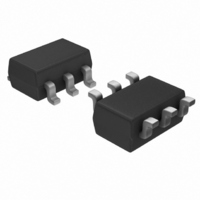
TC1240AECHTR Microchip Technology, TC1240AECHTR Datasheet - Page 8

TC1240AECHTR
Manufacturer Part Number
TC1240AECHTR
Description
IC CHARGE PUMP CONV SOT23A-6
Manufacturer
Microchip Technology
Type
Switched Capacitor (Charge Pump), Doublerr
Datasheet
1.TC1240AECHTR.pdf
(16 pages)
Specifications of TC1240AECHTR
Internal Switch(s)
Yes
Synchronous Rectifier
No
Number Of Outputs
1
Voltage - Output
-1.8 ~ -5.5 V, ±3.6 ~ ±11 V
Current - Output
20mA
Frequency - Switching
80kHz
Voltage - Input
2.5 ~ 5.5 V
Operating Temperature
-40°C ~ 85°C
Mounting Type
Surface Mount
Package / Case
SOT-23-6
Power - Output
600mW
Primary Input Voltage
5.5V
No. Of Outputs
1
Output Current
20mA
Voltage Regulator Case Style
SOT-23A
No. Of Pins
6
Operating Temperature Range
-40°C To +85°C
Svhc
No SVHC (15-Dec-2010)
Function
Step Up
Output Voltage
5 V to 11 V
Maximum Operating Temperature
85 C
Minimum Operating Temperature
- 40 C
Mounting Style
SMD/SMT
Lead Free Status / RoHS Status
Lead free / RoHS Compliant
Lead Free Status / RoHS Status
Lead free / RoHS Compliant, Lead free / RoHS Compliant
Available stocks
Company
Part Number
Manufacturer
Quantity
Price
Company:
Part Number:
TC1240AECHTR
Manufacturer:
MICROCHIP
Quantity:
12 000
Part Number:
TC1240AECHTR
Manufacturer:
MICROCHP
Quantity:
20 000
TC1240/TC1240A
The switching frequency in Equation 5-1b is defined as
one-half the oscillator frequency (i.e., F
The 1/(F
output resistance of an ideal switched capacitor circuit
(Figure 5-1 and Figure 5-2).
The output voltage ripple is given by Equation 5-2.
EQUATION 5-2:
FIGURE 5-1:
Model.
FIGURE 5-2:
Resistance.
DS21516C-page 8
V RIPPLE
V+
V+
R
SW
EQUIV
)(C
C
R
1
EQUIV
1
=
) term in Equation 5-1b is the effective
=
f
--------------------------------
2 F SW
F
(
1
SW
I
OUT
Ideal Switched Capacitor
Equivalent Output
x C
) C 2
(
1
C
C
)
2
2
+
2 I OUT
(
R
SW
) ESR C2
R
(
L
L
= F
V
V
OUT
OUT
OSC
)
/2).
5.3
In order to maintain the lowest output resistance and
output ripple voltage, it is recommended that low ESR
capacitors be used. Additionally, larger values of C
lower the output resistance and larger values of C
reduce output ripple (see Equation 5-1b).
Table 5-1 shows various values of C
corresponding output resistance values @ +25°C. It
assumes a 0.1Ω ESR
shows the output voltage ripple for various values of
C
current and 0.1Ω ESR
TABLE 5-1:
TABLE 5-2:
2
. The V
C
1
0.47
100
2.2
3.3
4.7
10
47
1
(µF)
Capacitor Selection
C
RIPPLE
0.47
1
100
2.2
3.3
4.7
10
47
1
(µF)
OUTPUT RESISTANCE
VS. C
OUTPUT VOLTAGE RIPPLE
VS. C
I
OUT
values assume 5mA output load
C2
R
TC1240
C1
5 mA
2003 Microchip Technology Inc.
.
OUT
1
2
28.5
19.5
15.5
13.6
12.5
12.2
47
17
(ESR = 0.1Ω)
(ESR = 0.1Ω)
and 0.9Ω R
(Ω)
TC1240/TC1240A
V
RIPPLE
142
6.7
2.5
1.6
67
30
20
14
SW
TC1240A
R
OUT
1
(mV)
. Table 5-2
20.5
10.5
9.3
8.3
8.1
35
14
12
and the
(Ω)
2
1
will
will


