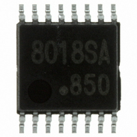
AN8018SA-E1V Panasonic - SSG, AN8018SA-E1V Datasheet - Page 16

AN8018SA-E1V
Manufacturer Part Number
AN8018SA-E1V
Description
IC MULTI CONFIG ADJ 50MA 16SSOP
Manufacturer
Panasonic - SSG
Type
Step-Down (Buck), Step-Up (Boost), Invertingr
Specifications of AN8018SA-E1V
Lead Free Status
Lead free
Internal Switch(s)
No
Synchronous Rectifier
No
Number Of Outputs
2
Voltage - Output
Adj to 15V
Current - Output
50mA
Frequency - Switching
20kHz ~ 1MHz
Voltage - Input
1.8 ~ 14 V
Operating Temperature
-30°C ~ 85°C
Mounting Type
Surface Mount
Package / Case
16-SSOP
Power - Output
135mW
Other names
AN8018SAE1V
AN8018SAE1VTR
AN8018SAE1VTR
Available stocks
Company
Part Number
Manufacturer
Quantity
Price
Company:
Part Number:
AN8018SA-E1V
Manufacturer:
PANASONIC
Quantity:
1 347
AN8018SA
I Application Notes (continued)
16
[6] Time constant setting method for timer latch short-circuit protection circuit
protection compares the error amplifier 1 output FB1 with the reference voltage of 0.9 V for channel 1 side, and the
error amplifier 2 output FB2 with the reference voltage of 0.22 V for channel 2 side at all the time.
output and the short-circuit protection comparator also keeps the balance. At this moment, the output transistor Q1 is
in the conductive state and the S.C.P. terminal is held to approximately 60 mV.
the error amplifier 1 block to the short-circuit protection comparator, the short-circuit protection comparator outputs
the low-level signal to cut off the output transistor Q1. Also, when the load conditions for channel 2 side suddenly
change and low-level signal (0.22 V or less) is inputted from the error amplifier 2 block to the short-circuit protection
comparator, the short-circuit protection comparator outputs the low-level signal to cut off the output transistor Q1.
The capacitor C
to approximately 1.19 V with the constant current of approximately 1.1 µA, the latch circuit is set, the output terminal
is fixed to low level, and the dead-time is set to 100%. Once the latch circuit is set, the S.C.P. terminal is discharged
to approximately 40 mV, However, the latch circuit is not reset unless the power for the latch circuit is turned off or
restarted by the on/off control.
considered to be short-circuited state so that the S.C.P.
terminal voltage starts charging. It is necessary to set the
external capacitor so as to start up the DC-DC converter
output voltage before setting the latch circuit in the later
stage. Especially, pay attention to the delay of the start-up
time when applying the soft-start.
The constructional block diagram of protection latch circuit is shown in figure 6. The comparator for short-circuit
When the load conditions of DC-DC converter output is stabilized, there is no fluctuation of error amplifier
When the load conditions for channel 1 side suddenly change and high-level signal (0.9 V or more) is input from
When the power supply is turned on, the output is
1.19 V = I
∴ t
PE
IN+2 14
IN+1
IN−1
FB1 5
FB2 13
[s] = 1.08 × C
SCP
CHG
3
4
connected to the S.C.P. terminal starts charging. When the external capacitor C
Error amp.1
Error amp.2
×
1.19 V
C
t
PE
SCP
SCP
0.22 V
control
On/off
0.9 V
Figure 6. Short-circuit protection circuit
S.C.P.
comp.
SDH00008CEB
Q1
1.1 µA
High-level detection comp.
1.19 V
Figure 5. S.C.P. terminal charging waveform
1.19
0.06
V
SCP
U.V.L.O.
Short-circuit detection time t
R
S
Latch
[V]
Q
Internal
reference
Output cut-off
SCP
has been charged
PE
t [s]


