LT1074IT Linear Technology, LT1074IT Datasheet
LT1074IT
Specifications of LT1074IT
Available stocks


Related parts for LT1074IT


LT1074IT Summary of contents
Page 1
... A 7-pin TO-220 package is also available which allows current limit to be adjusted down to zero. In addition, full micropower shutdown can be programmed. See Application Note 44 for design details. A fixed 5V output, 2A version is also available. See LT1076-5. , LTC and LT are registered trademarks of Linear Technology Corporation USE MBR340 FOR LT1076 ...
Page 2
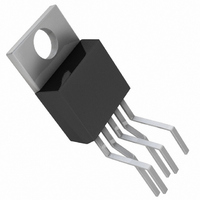
... V SW LT1076CK K PACKAGE 4-LEAD TO-3 METAL CAN LT1076HVCK = 2.5°C, θ = 35°C LT1076MK = 4°C, θ = 35°C LT1076HVMK LT1074CT FRONT VIEW LT1074HVCT LT1074IT GND LT1074HVIT LT1076CT 1 FB LT1076HVCT T PACKAGE LT1076IT 5-LEAD PLASTIC TO-220 LT1076HVIT STRAIGHT LEADS, ORDER FLOW 06 = 2.5°C, θ = 50°C 4° ...
Page 3
ELECTRICAL CHARACTERISTICS temperature range, otherwise specifications are at T PARAMETER CONDITIONS Switch “On” Voltage (Note 2) LT1074 LT1076 Switch “Off” Leakage LT1074 LT1076 Supply Current (Note 3) V 40V < Minimum Supply Voltage Normal Mode Startup Mode (Note ...
Page 4
LT1074/LT1076 ELECTRICAL CHARACTERISTICS Note 1: Absolute Maximum Ratings are those values beyond which the life of a device may be impaired. Note 2: To calculate maximum switch “on” voltage at currents between low and high conditions, a linear interpolation may ...
Page 5
W BLOCK DIAGRA DESCRIPTIO A switch cycle in the LT1074 is initiated by the oscillator setting the R/S latch. The pulse that sets the latch also locks out the switch via gate G1. The effective width of this pulse is ...
Page 6
LT1074/LT1076 W U TYPICAL PERFOR A CE CHARACTERISTICS V Pin Characteristics C 200 150 V ADJUSTED FOR 100 –50 SLOPE ≈ 400kΩ –100 ≤ –150 ...
Page 7
W U TYPICAL PERFOR A CE CHARACTERISTICS Supply Current (Shutdown) 300 250 200 150 100 INPUT VOLTAGE (V) LT1074•TPC13 Reference Shift with Ripple Voltage –10 TRI WAVE –20 ...
Page 8
LT1074/LT1076 DESCRIPTIO S V PIN IN The V pin is both the supply voltage for internal control IN circuitry and one end of the high current switch important, especially at low input voltages , that ...
Page 9
DESCRIPTIO S current is well controlled even when switch duty cycle must be extremely low. Theoretical switch “on” time for a buck converter in continuous mode is OUT • V ...
Page 10
LT1074/LT1076 DESCRIPTIO S µ 300 A µ SHUTDOWN – PIN C1 2.3V + – C2 0.3V + Figure 5. Shutdown Circuitry Undervoltage Lockout Undervoltage lockout point is set by R1 and R2 in Figure 6. ...
Page 11
DESCRIPTIO S I PIN LIM The I pin is used to reduce current limit below the LIM preset value of 6.5A. The equivalent circuit for this pin is shown in Figure 8. TO LIMIT V IN CIRCUIT ...
Page 12
LT1074/LT1076 DESCRIPTIO S µ X1.8 2.21V ALL CURRENTS SHOWN ARE AT NULL CONDITION mid frequencies V • • 2π • high frequencies ...
Page 13
U TYPICAL APPLICATIO † 20V TO 35V + C3 200 50V * PULSE ENGINEERING #PE±65282 ** MOTOROLA MBR2030CTL † IF INPUT VOLTAGE IS BELOW 20V, MAXIMUM OUTPUT CURRENT WILL BE REDUCED. SEE AN44 + * = 1% ...
Page 14
LT1074/LT1076 PACKAGE DESCRIPTIO 0.320 – 0.350 0.420 – 0.480 (10.67 – 12.19) 0.060 0.256 (1.524) (6.502) 0.060 0.183 (1.524) (4.648) 0.075 (1.905) 0.300 (7.620) BOTTOM VIEW OF DD PAK HATCHED AREA IS SOLDER PLATED COPPER HEAT SINK ...
Page 15
... Information furnished by Linear Technology Corporation is believed to be accurate and reliable. However, no responsibility is assumed for its use. Linear Technology Corporation makes no represen- tation that the interconnection of its circuits as described herein will not infringe on existing patent rights Package ...
Page 16
... AT THE SEATING PLANE T7 (TO-220) 0399 Up to 1.25A, SO-8 OUT Up to 4.25A, SO-8/DD OUT Up to 0.5A, SO-8 OUT Up to 50A, Current Mode OUT =1.2V, TSSOP-16E, SO8 Package µF LT/CPI 0202 1.5K REV D • PRINTED IN USA © LINEAR TECHNOLOGY CORPORATION 1994 sn1074 1074fds ...