MIC23250-S4YMT TR Micrel Inc, MIC23250-S4YMT TR Datasheet
MIC23250-S4YMT TR
Specifications of MIC23250-S4YMT TR


Related parts for MIC23250-S4YMT TR


MIC23250-S4YMT TR Summary of contents
Page 1
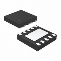
... At higher loads the MIC23250 provides a constant switching frequency around 4MHz while providing peak efficiencies up to 94%. The MIC23250 fixed output voltage option is available in a 10-pin 2mm x 2mm Thin MLF options is available in a 12-pin 2.5mm x 2.5mm Thin MLF The MIC23250 is designed to operate over the junction operating range from – ...
Page 2
... WV3 MIC23250-C4YMT WV2 MIC23250-W4YMT WV4 MIC23250-G4YMT WV5 MIC23250-S4YMT 1WV MIC23250-GFHYMT WV1 MIC23250-SKYMT 5WV MIC23250-AAYMT 4WV Notes: 1) Additional voltage options available (0.8V to 3.3V). Contact Micrel for details. ® 2) Thin MLF is GREEN RoHS compliant package. Lead finish is NiPdAu. Mold compound is Halogen Free. June 2010 ...
Page 3
... Feedback VOUT2 (Input): Connect resistor divider at this node to set output voltage. Resistors should be selected based on a nominal VFB of 0.72V. 3 FB1 1 12 FB2 SNS1 2 11 SNS2 EN1 3 10 EN2 AGND 4 9 AVIN SW1 5 8 SW2 PGND 6 7 VIN ® 12-Pin 2.5mmx2.5mm Thin MLF (MT) Adjustable Output (Top View) M9999-061110-E MIC23250 ...
Page 4
... LOAD = 20mA 0.4 LOAD < 2.5V 0.5 OUTNOM ≥ 2.5V 0.5 OUTNOM 0.6 0.8 4 260 0.5 0.8 0.1 160 40 MIC23250 IN ≤ +125°C J Max Units 2. µA 4 µA +2 %/V %/ Ω Ω MHz µs 1.2 ...
Page 5
... OUT 100 VIN = 3.0V 90 VIN = 2. VIN = 3.6V 60 VIN = 4. 1µ 4.7µF OUT 100 1000 OUTPUT CURRENT (mA) 5 MIC23250 Switching Frequency vs. Output Current 4.7µH 4MHz 1µ 2.2µ 1.8V OUT C = 4.7µF OUT 0. 100 1000 OUTPUT CURRENT (mA) Output Voltage vs ...
Page 6
... Dual Output Efficiency 100 VIN = 3. VIN = 4.2V 70 VIN = 3. 1.575V OUT1 V = 1.8V 30 OUT2 Load1 = Load2 1µ 4.7µF OUT1 OUT2 100 1000 OUTPUT CURRENT (mA) 6 MIC23250 Efficiency V = 3.3V OUT 100 VIN = 4. VIN = 5.5V VIN = 5. 1µ 4.7µF OUT 100 1000 OUTPUT CURRENT (mA) M9999-061110-E ...
Page 7
... Micrel, Inc. Functional Characteristics June 2010 7 MIC23250 M9999-061110-E ...
Page 8
... Micrel, Inc. Functional Characteristics (Continued) June 2010 8 MIC23250 M9999-061110-E ...
Page 9
... Micrel, Inc. Functional Characteristics (Continued) June 2010 9 MIC23250 M9999-061110-E ...
Page 10
... Micrel, Inc. Functional Diagram V IN EN1 SW1 FB1 SNS1 June 2010 MIC23250 Simplified Fixed Output Block Diagram ENABLE ENABLE LOGIC LOGIC GATE GATE DRIVES DRIVES CONTROL CONTROL LOGIC LOGIC T TIMER & T TIMER & Zero X SOFT START SOFT START I SENSE Current Limit ...
Page 11
... FB1/FB2 (Adjustable Output Only) The feedback pins (FB1/FB2) are two extra pins that can only be found on the MIC23250-AAYMT devices. It allows the regulated output voltage to be set by applying an external resistor network. The internal reference voltage is 0.72V and the recommended value of R 10% of 442kΩ ...
Page 12
... DCR can represent a significant Considerations. Compensation The MIC23250 is designed to be stable with a 0.47µH to 4.7µH inductor with a minimum of 2.2µF ceramic (X5R) output capacitor. For the adjustable MIC23250, the total feedback resistance should be kept around 1MΩ to reduce current loss down the feedback resistor network ...
Page 13
... By using 442 120 the HyperLight Load™ mode the MIC23250 is able to 442 120 maintain high efficiency at low output currents. 442 120 Over 100mA, efficiency loss is dominated by MOSFET ...
Page 14
... PWM mode is a function of the input voltage (V voltage (V frequency (f). This is illustrated in the graph below. Since the inductance range of MIC23250 is from 0.47µH to 4.7µH, the device may then be tailored to enter HyperLight Load™ mode or PWM mode at a specific load current by selecting the appropriate inductance. For example, in the graph below, when the inductance is 4.7µ ...
Page 15
... Micrel, Inc. MIC23250 Typical Application Circuit (Fixed Output) Bill of Materials Item Part Number C1, C2, C3 C1608X5R0J475K C4 VJ0603Y103KXXAT R1, R2 CRCW06031002FKEA LQM21PN1R0MC0D LQH32CN1R0M33 LQM31PN1R0M00 L1, L2 GLF251812T1R0M LQM31PNR47M00 MIPF2520D1R5 EPL2010-102 U1 MIC23250-xxYMT Notes: 1. TDK: www.tdk.com. 2. Vishay: www.vishay.com. 3. Murata: www.murata.com. 4. FDK: www.fdk.co.jp. 5. Coilcraft: www.coilcraft.com. 6. Micrel, Inc: www.micrel.com. ...
Page 16
... Micrel, Inc. PCB Layout Recommendations (Fixed Output) June 2010 Top Layer Bottom Layer 16 MIC23250 M9999-061110-E ...
Page 17
... Micrel, Inc. MIC23250 Typical Application Circuit (Adjustable Output) Bill of Materials Item Part Number C1, C2, C3 C1608X5R0J475K C4 VJ0603Y103KXXAT C5, C6 VJ0603Y121KXAAT R1, R2 CRCW06031002FKEA R3, R5 CRCW06036653FKEA R4, R6 CRCW06034423FKEA LQM21PN1R0MC0D LQH32CN1R0M33 LQM31PN1R0M00 L1, L2 GLF251812T1R0M LQM31PNR47M00 MIPF2520D1R5 EPL2010-102 U1 MIC23250-AAYMT Notes: 1. TDK: www.tdk.com. 2. Vishay: www.vishay.com. 3. Murata: www.murata.com. 4. FDK: www.fdk.co.jp. ...
Page 18
... Micrel, Inc. PCB Layout Recommendations (Adjustable Output) June 2010 Top Layer Bottom Layer 18 MIC23250 M9999-061110-E ...
Page 19
... Micrel, Inc. Package Information (Fixed Output) June 2010 ® 10-Pin 2mm x 2mm Thin MLF (MT) 19 MIC23250 M9999-061110-E ...
Page 20
... Purchaser’s use or sale of Micrel Products for use in life support appliances, devices or systems is a Purchaser’s own risk and Purchaser agrees to fully June 2010 12-Pin 2.5mm x 2.5mm Thin MLF indemnify Micrel for any damages resulting from such use or sale. © 2007 Micrel, Incorporated. 20 ® (MT) http://www.micrel.com M9999-061110-E MIC23250 nt ...