SC194BMLTRT Semtech, SC194BMLTRT Datasheet
SC194BMLTRT
Specifications of SC194BMLTRT
Available stocks


Related parts for SC194BMLTRT


SC194BMLTRT Summary of contents
Page 1
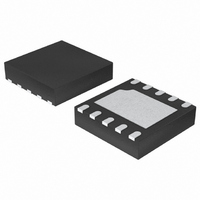
... Lead-free package — 3mm x 3mm MLPD Applications PDA Pocket PC and Smart Phones USB Powered Modems CPUs and DSPs PC Cards and Notebooks xDSL Applications Standard 5-V to 3.3-V Conversion SC194B VIN LX 4.7μH EN SYNC/PWM VOUT VID0 VID1 PGND MODE GND 1 SC194B L1 V OUT 3. OUT 22μF www.semtech.com ...
Page 2
... Tested according to JEDEC standard JESD22-A114-B. Electrical Characteristics Unless otherwise noted 3.3V OUT Parameter Input Voltage Range VOUT Accuracy VOUT Temperature Accuracy Line Regulation Load Regulation (PWM) PSAVE Regulation P-Channel On Resistance N-Channel On Resistance Start-Up Time P-Channel Current Limit © 2006 Semtech Corp. Symbol OUT V LX θ ( ...
Page 3
... Oscillator Frequency SYNC Frequency (upper) SYNC Frequency (lower) UVLO Threshold (upper) UVLO Hysteresis Thermal Shutdown Thermal Shutdown Hysteresis Logic Input High Logic Input Low Logic Input Current High Logic Input Current Low © 2006 Semtech Corp. Symbol Conditions SYNC/PWM = GND 1. OUT OUT(Programmed) I ...
Page 4
... Semtech Corp. Ordering Information DEVICE SC194BMLTRT SC194BEVB Ordering Information Notes Lead-free packaging only. This product is fully WEEE and RoHS compliant. 2) Available in tape and reel only. A reel contains 3000 devices. ...
Page 5
... LX Inductor connection to the switching FETs THERMAL Pad is for heatsinking purposes T PAD plane using multiple vias. © 2006 Semtech Corp. to select 100% duty cycle function and MODE = GND to IN — Tie to V for forced PWM mode or GND to allow the part to IN — ...
Page 6
... POWER MANAGEMENT Block Diagram EN 4 OSC & Slope SYNC/ 3 Generator PWM 500mV Ref 2 MODE 7 VID1 Voltage Select 6 VID0 5 VOUT © 2006 Semtech Corp. Plimit Amp Control PWM Comp Error Amp PSAVE Comp 6 SC194B 1 Current Amp 10 Logic Nlimit Amp 9 8 www.semtech.com VIN LX ...
Page 7
... Protection Features The SC194B provides the following protection features: • Thermal shutdown • Current limit © 2006 Semtech Corp. • Over-voltage protection • Soft-start Thermal Shutdown The device has a thermal shutdown feature to protect the SC194B if the junction temperature exceeds 145°C. In thermal shutdown the on-chip power devices are disabled, tri-stating the LX output ...
Page 8
... V OUT -2% Inductor Current 0 A Time © 2006 Semtech Corp. 100% Duty Cycle Operation The 100% duty cycle mode may be selected by connecting the MODE pin high. This will allow the SC194B to maintain output regulation under low input voltage/high output voltage conditions. In 100% duty cycle operation, as the input supply drops toward the output voltage, the PMOS on-time increases linearly above the maximum value in fi ...
Page 9
... I OUT(ESR) OUT(ESR) L(ripple) L(ripple) © 2006 Semtech Corp. Capacitors with X7R or X5R ceramic dielectric are strongly recommended for their low ESR and superior temperature and voltage characteristics. Y5V capacitors should not be used as their temperature coeffi cients make them unsuitable for this application. Table 2 lists the manufacturers of recommended capacitor options ...
Page 10
... Place the inductor and fi lter capacitors as close to the device as possible and use short wide traces between the power components. GND V IN © 2006 Semtech Corp. 2. Route the output voltage feedback path away from the inductor and LX node to minimize noise and magnetic interference. 3. ...
Page 11
... V =4.2V, PWM 0.0001 0.001 0.01 I (A) OUT Effi ciency vs. Input Voltage V 100 V =3.3V,PSAVE OUT =2.5V,PWM OUT 2.5 3 3.5 4 4.5 Vin (V) I =500 mA(PWM)/50 mA(PSAVE) OUT © 2006 Semtech Corp. = 3.6V OUT 100 0.1 1 0.0001 = 3.0V OUT 100 =5.0V, PWM 0 0.0001 = 3.3V ...
Page 12
... V =5.0V,PWM IN 3.28 3.27 -50 -40 -30 -20 - (°C) A Quiescent Current vs. Input Voltage PWM Mode 6 5.5 T =85 ° =25 A 4.5 4 3.5 3 3.5 4 4.5 2 (V) IN © 2006 Semtech Corp. IN 3.292 3.29 3.288 3.286 3.284 3.282 3.28 3.278 5 5 0.22 T =-40 ° 0.20 0.18 ° ...
Page 13
... V (V) IN 100% Duty Cycle Mode Time (400ns/div) Condition V = 3.8V 1A 3.3V IN OUT OUT PWM Operation Time (1μs/div) Condition V =5V, l =50mA, V =3.3V IN OUT OUT © 2006 Semtech Corp. Switching Frequency vs. Temperature 1050 1040 1030 V =5.5V IN 1020 1010 ° 1000 ° 990 ° ...
Page 14
... Typical Characteristics (Cont.) PWM Start-Up Time (400μs/div) Condition 10mA 3.3V IN OUT OUT Load Transient Response PSAVE Time (400μs/div) Condition 100mA OUT © 2006 Semtech Corp. Load Transient Response PWM V (2V/div (2V/div) OUT I (200mA/div) IN Condition V V (200mV/div) OUT I (500VmA/div)) ...
Page 15
... Dynamic Voltage Positioning for Reduced System Dissipation in "Sleep" Modes V IN 2. 10μF From uP Sleep controller V = 2.5V with PSAVE and 100% Duty Cycle OUT V IN 2. 10μF © 2006 Semtech Corp. L1 SC194B VIN LX EN 4.7μH SYNC/PWM VOUT VID0 VID1 PGND MODE GND L1 SC194B VIN LX 4.7μ ...
Page 16
... POWER MANAGEMENT Outline Drawing - MLP-10 A PIN 1 INDICATOR (LASER MARK) aaa C 1 LxN N e NOTES: 1. CONTROLLING DIMENSIONS ARE IN MILLIMETERS (ANGLES IN DEGREES). 2. COPLANARITY APPLIES TO THE EXPOSED PAD AS WELL AS TERMINALS. © 2006 Semtech Corp SEATING PLANE bxN bbb SC194B DIMENSIONS INCHES MILLIMETERS DIM MIN ...
Page 17
... POWER MANAGEMENT Land Pattern - MLP- NOTES: 1. THIS LAND PATTERN IS FOR REFERENCE PURPOSES ONLY. CONSULT YOUR MANUFACTURING GROUP TO ENSURE YOUR COMPANY'S MANUFACTURING GUIDELINES ARE MET. Contact Information Phone: (805) 498-2111 Fax: (805) 498-3804 © 2006 Semtech Corp. DIMENSIONS K DIM INCHES C (.112) G .075 H .055 ...