IR3800AMTRPBF International Rectifier, IR3800AMTRPBF Datasheet
IR3800AMTRPBF
Specifications of IR3800AMTRPBF


Related parts for IR3800AMTRPBF

IR3800AMTRPBF Summary of contents
Page 1
SupIRBuck TM WIDE-INPUT VOLTAGE, SYNCHRONOUS BUCK REGULATOR Features • Wide Input Voltage Range 2.5V to 21V • Wide Output Voltage Range 0.6V to 12V • Continuous 14A Load Capability • 300kHz High Frequency Operation • Programmable Over-Current Protection • Hiccup ...
Page 2
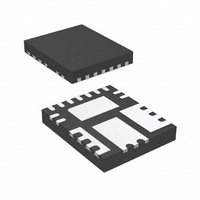
... To 150°C -40°C To 150°C JEDEC, JESD22-A114 JEDEC Level 3 @ 260 PGnd AGnd COMP AGnd AGnd SS OCSet Fig. 2: Package outline (Top view) PACKAGE PIN COUNT DESCRIPTION IR3800AMTRPbF 15 IR3800AMTR1PbF 15 PD-60353 IR3800AMPbF o C θ θ PCB - PARTS PER REEL 4000 ...
Page 3
Block Diagram Fig. 3. Simplified block diagram of the IR3800A. 11/04/08 PD-60353 IR3800AMPbF 3 ...
Page 4
Pin Description Pin Name Connect 2 Fb Inverting input to the error amplifier. This pin is connected directly to the output of the regulator via resistor divider to set the output voltage and provide feedback to the ...
Page 5
Recommended Operating Conditions Symbol Definition V Input Voltage in V Supply Voltage cc V Supply Voltage c V Output Voltage o Note1 I Output Current o T Junction Temperature j Electrical Specifications Unless otherwise specified, these specification apply over Vin=V ...
Page 6
Parameter SYM Oscillator Frequency F S Ramp Amplitude V ramp Min Pulse Width D min(ctrl) Max Duty Cycle D max Error Amplifier Input Bias Current I FB1 Input Bias Current I FB2 Source/Sink Current I(source/Sink) Transconductance gm Soft Start/SD Soft ...
Page 7
TYPICAL OPERATING CHARACTERISTICS (-40 Icc(static) 13.0 12.0 11.0 10.0 9.0 8.0 7.0 -40 - Tem p[oC] Icc(dynam ic) 22.0 21.0 20.0 19.0 18.0 17.0 16.0 15.0 14.0 13.0 -40 - Tem p[oC] ...
Page 8
Circuit Description THEORY OF OPERATION The IR3800A is a voltage synchronous regulator and operates with a fixed 300kHz switching frequency, allowing the use of small external components. The output voltage is set by feedback pin (Fb) and the internal reference ...
Page 9
Soft-Start The IR3800A has programmable soft-start to control the output voltage rise and limit the inrush current during start-up. To ensure correct start-up, sequence initiates when Vcc and Vc rise above their threshold and generate the Power On Ready (POR) ...
Page 10
Over-Current Protection The over-current protection is performed by sensing current through the R DS(on) side MOSFET. This method enhances the converter’s efficiency and reduces cost by eliminating a current sense resistor. As shown in figure 7, an external resistor (R ...
Page 11
Application Information Design Example: The following example is a typical application for the IR3800A. The application circuit is shown in page 17 V max ) = ...
Page 12
Input Capacitor Selection The input filter capacitor should be selected based on how much ripple the supply can tolerate on the DC input line. The ripple current generated during the on time of upper MOSFET should be provided by the ...
Page 13
Feedback Compensation The IR3800A is a voltage mode controller; the control loop is a single voltage feedback path including error amplifier and error comparator. To achieve fast transient response and accurate output regulation, a compensation circuit is necessary. The goal ...
Page 14
To cancel one of the LC filter poles, place the zero before the LC filter resonant frequency pole π ...
Page 15
Based on the frequency of the zero generated by the output capacitor and its ESR versus crossover frequency, the compensation type can be different. The table below shows the compensation types and location of crossover frequency. Compensator F vs. F ...
Page 16
Programming the Current-Limit The Current-Limit threshold can be set by connecting a resistor (R ) from drain of the SET low-side MOSFET to the OCSet pin. The resistor can be calculated by using equation (3). The R has a positive ...
Page 17
Typical Application for IR3800A Fig.16: Typical Application circuit for 12V to 1.8V at 14A using ceramic output capacitors 11/04/08 12V to 1.8V @ 14A PD-60353 IR3800AMPbF 17 ...
Page 18
PCB Metal and Components Placement The lead lands (the 11 IC pins) width should be equal to the nominal part lead width. The minimum lead-to-lead spacing should be ≥ 0.2mm to minimize shorting. Lead land length should be equal to ...
Page 19
Solder Resist It is recommended that the lead lands are Non Solder Mask Defined (NSMD). The solder resist should be pulled away from the metal lead lands by a minimum of 0.025mm to ensure NSMD pads. The land pad should ...
Page 20
Stencil Design • The Stencil apertures for the lead lands should be approximately 80% of the area of the lead lads. Reducing the amount of solder deposited will minimize the occurrences of lead shorts. If too much solder is deposited ...
Page 21
IR WORLD HEADQUARTERS: This product has been designed and qualified for the Consumer market. 11/04/08 IR3800AMPbF 233 Kansas St., El Segundo, California 90245, USA Tel: (310) 252-7105 Visit us at www.irf.com for sales contact information Data and specifications subject to ...