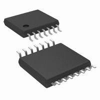
LM2852YMXA-1.2/NOPB National Semiconductor, LM2852YMXA-1.2/NOPB Datasheet - Page 11

LM2852YMXA-1.2/NOPB
Manufacturer Part Number
LM2852YMXA-1.2/NOPB
Description
IC REG SYNC BUCK 2A 1.2V 14TSSOP
Manufacturer
National Semiconductor
Series
PowerWise®, SIMPLE SWITCHER®r
Type
Step-Down (Buck)r
Datasheet
1.LM2852YMXA-3.3NOPB.pdf
(14 pages)
Specifications of LM2852YMXA-1.2/NOPB
Internal Switch(s)
Yes
Synchronous Rectifier
Yes
Number Of Outputs
1
Voltage - Output
1.2V
Current - Output
2A
Frequency - Switching
500kHz
Voltage - Input
2.85 ~ 5.5 V
Operating Temperature
-40°C ~ 125°C
Mounting Type
Surface Mount
Package / Case
14-TSSOP Exposed Pad, 14-eTSSOP 14-HTSSOP
Package
14TSSOP EP
Minimum Input Voltage
2.85 V
Maximum Input Voltage
5.5 V
Switching Frequency
500(Typ) KHz
Operating Supply Voltage
1.5 to 5.5 V
Maximum Output Current
2 A
Output Type
Fixed
Output Voltage
1.2 V
Efficiency
88 %
For Use With
LM2852Y-1.2EVAL - BOARD EVAL LM2852Y-1.2
Lead Free Status / RoHS Status
Lead free / RoHS Compliant
Power - Output
-
Other names
*LM2852YMXA-1.2
*LM2852YMXA-1.2/NOPB
LM2852YMXA-1.2
*LM2852YMXA-1.2/NOPB
LM2852YMXA-1.2
Available stocks
Company
Part Number
Manufacturer
Quantity
Price
Company:
Part Number:
LM2852YMXA-1.2/NOPB
Manufacturer:
NS
Quantity:
46
Applications Information
CHOOSING AN INDUCTANCE VALUE
The current ripple present in the output filter inductor is
determined by the input voltage, output voltage, switching
frequency and inductance according to the following equa-
tion:
where ∆I
cycle V
pin, V
switching frequency and L is the inductance of the output
filter inductor. Knowing the current ripple is important for
inductor selection since the peak current through the induc-
tor is the load current plus one half the ripple current. Care
must be taken to ensure the peak inductor current does not
reach a level high enough to trip the current limit circuitry of
the LM2852.
As an example, consider a 5V to 1.2V conversion and a
500kHz switching frequency. According to Table 1, a 15µH
inductor may be used. Calculating the expected peak-to-
peak ripple,
OUT
OUT
Inductance (µH)
L
is the peak-to-peak current ripple, D is the duty
/V
is the output voltage of the switcher, f is the
IN
6.8
10
10
12
15
15
18
22
22
22
27
33
33
, V
1
1
7
IN
is the input voltage applied to the PVIN
TABLE 2. LM2852 Output Filter Inductors
(Continued)
MSS1038-702NBC
MSS1038-103NBC
MSS1038-123NBC
MSS1038-153NBC
MSS1038-183NBC
MSS1038-223NBC
MSS1038-273NBC
MSS1038-333NBC
DO1813P-102HC
DO1608C-102
DO3316P-682
DO3316P-103
DO3316P-223
DO3340P-223
DO3340P-333
D03316P-153
Part Number
11
The maximum inductor current for a 2A load would therefore
be 2A plus 60.8 mA, 2.0608A. As shown in the ripple equa-
tion, the current ripple is inversely proportional to induc-
tance.
OUTPUT FILTER INDUCTORS
Once the inductance value is chosen, the key parameter for
selecting the output filter inductor is its saturation current
(I
as the current at which the inductance of the coil falls to a
certain percentage of the nominal inductance. The I
inductor used in an application should be greater than the
maximum expected inductor current to avoid saturation. Be-
low is a table of inductors that may be suitable in LM2852
applications.
sat
) specification. Typically I
sat
is given by the manufacturer
Coilcraft
Coilcraft
Coilcraft
Coilcraft
Coilcraft
Coilcraft
Coilcraft
Coilcraft
Coilcraft
Coilcraft
Coilcraft
Coilcraft
Coilcraft
Coilcraft
Coilcraft
Coilcraft
Vendor
www.national.com
sat
of an


