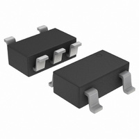
NCP1406SNT1G ON Semiconductor, NCP1406SNT1G Datasheet - Page 5

NCP1406SNT1G
Manufacturer Part Number
NCP1406SNT1G
Description
IC CONV DC-DC 25MA/25V SOT23-5
Manufacturer
ON Semiconductor
Type
Step-Down (Buck), Step-Up (Boost), Invertingr
Datasheet
1.NCP1406SNT1G.pdf
(19 pages)
Specifications of NCP1406SNT1G
Internal Switch(s)
Yes
Synchronous Rectifier
No
Number Of Outputs
1
Voltage - Output
Adj to 25V
Current - Output
25mA
Frequency - Switching
1MHz
Voltage - Input
1.4 ~ 5.5 V
Operating Temperature
-40°C ~ 85°C
Mounting Type
Surface Mount
Package / Case
TSOT-23-5, TSOT-5, TSOP-5
Power - Output
500mW
Mounting Style
SMD/SMT
Lead Free Status / RoHS Status
Lead free / RoHS Compliant
Other names
NCP1406SNT1G
NCP1406SNT1GOSTR
NCP1406SNT1GOSTR
Available stocks
Company
Part Number
Manufacturer
Quantity
Price
Part Number:
NCP1406SNT1G
Manufacturer:
ON/安森美
Quantity:
20 000
4. Recommended maximum V
5. Guaranteed by design, not tested.
ELECTRICAL CHARACTERISTICS
otherwise noted.)
ON/OFF TIMING CONTROL
LX (PIN 5)
CE (PIN 1)
TOTAL DEVICE
Minimum Off Time (V
Maximum On Time (Current Not Asserted)
Maximum Duty Cycle
Minimum Startup Voltage (I
Minimum Startup Voltage Temperature Coefficient (T
Minimum Hold Voltage (I
Soft−Start Time
Internal Switch Voltage (Note 4) (Note 5)
LX Pin On−State Resistance (V
Current Limit (When I
Off−State Leakage Current (V
CE Input Voltage (V
CE Input Current
Supply Voltage
Undervoltage Lockout (V
Feedback Voltage
Feedback Pin Bias Current (V
Operating Current 1 (V
Operating Current 2 (V
Off−State Current (V
Thermal Shutdown (Note 5)
Thermal Shutdown Hysteresis (Note 5)
LX switch protection circuit) (Note 5)
High State, Device Enabled
Low State, Device Disabled
High State, Device Enabled (V
Low State, Device Disabled (V
DD
DD
DD
LX
FB
DD
= 3.0 V, V
= 5.0 V, V
= 3.0 V, V
reaches I
OUT
DD
= 0 V, V
= V
OUT
Falling)
= 0 mA)
CE
LX
OUT
FB
= 0 mA)
LX
= 26 V)
FB
= V
= 1.19 V)
CE
LIM
DD
FB
DD
DD
up to 25 V.
= 0.4 V, V
Characteristic
= 0 V)
FB
= 0 V)
, the LX switch is turned off by the
= V
= 0 V)
= V
= 5.5 V, V
= 3.0 V, Not Switching)
CE
CE
(V
= 3.0 V, Maximum Duty Cycle)
= 5.5 V)
OUT
DD
CE
= 5.0 V)
= 25 V, T
= V
A
FB
= −40 to +85°C)
= 0 V)
A
http://onsemi.com
= −40_C to +85_C for min/max values, typical values are at T
T
A
5
= −40 to +85°C
T
A
= 25°C
V
Symbol
V
I
T
R
I
DV
CE(high)
V
CE(low)
D
CE(high)
V
V
CE(low)
SDHYS
I
I
I
I
sw(on)
V
V
T
V
I
UVLO
t
LKG
I
DD1
DD2
OFF
t
t
LIM
MAX
start
hold
SS
off
FB
on
DD
FB
SD
start
LX
1.178
1.170
−500
0.08
0.58
Min
0.9
1.4
84
−
−
−
−
−
−
−
−
−
−
−
−
−
−
−
−
−
1.190
1.190
−150
0.13
0.90
0.80
Typ
140
1.8
1.6
1.7
3.0
0.7
0.1
1.0
0.7
0.3
90
10
15
15
10
−
−
−
−
A
= 25_C, unless
1.202
1.210
Max
0.20
1.40
500
2.0
1.9
8.0
1.0
0.3
5.5
1.3
1.5
1.3
96
26
45
25
−
−
−
−
−
−
−
mV/°C
Unit
ms
mA
mA
nA
nA
nA
mA
mA
ms
ms
°C
°C
%
W
V
V
V
A
V
V
V
V
V


