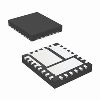
MIC26600YJL TR Micrel Inc, MIC26600YJL TR Datasheet

MIC26600YJL TR
Specifications of MIC26600YJL TR
Related parts for MIC26600YJL TR
MIC26600YJL TR Summary of contents
Page 1
... Typical Application Hyper Speed Control, SuperSwitcher II and Any Capacitor are trademarks of Micrel, Inc. MLF and MicroLeadFrame are registered trademarks of Amkor Technology, Inc. Micrel Inc. • 2180 Fortune Drive • San Jose, CA 95131 • USA • tel +1 ( September 2010 Features • ...
Page 2
Micrel, Inc. Ordering Information Part Number Voltage Switching Frequency MIC26600YJL Adjustable Pin Configuration Pin Description Pin Pin Name Pin Function Number 13,14,15, High-Side N-internal MOSFET Drain Connection (Input): The PV PVIN 4.5V to 26V. Input capacitors between the PVIN pins ...
Page 3
Micrel, Inc. Pin Description (Continued) Pin Pin Name Pin Function Number Boost (Output): Bootstrapped voltage to the high-side N-channel internal MOSFET driver. A Schottky 20 BST diode is connected between the VDD pin and the BST pin. A boost capacitor ...
Page 4
Micrel, Inc. Absolute Maximum Ratings to PGND................................................ −0.3V to +28V PGND ....................................................−0. PGND ................................................... −0. PGND .............................. −0. ........................................................ −0.3V ...
Page 5
Micrel, Inc. Electrical Characteristics 12V 5V; V – BST Parameter Short Circuit Protection Current-Limit Threshold Short-Circuit Current Internal FETs Top-MOSFET R DS (ON) Bottom-MOSFET R DS (ON) SW Leakage Current ...
Page 6
Micrel, Inc. Typical Characteristics V Operating Supply Current IN vs. Input Voltage 10.0 8.0 6.0 4 1.2V OUT OUT 2 SWITCHING 0 INPUT VOLTAGE (V) Feedback Voltage ...
Page 7
Micrel, Inc. Typical Characteristics (Continued) V Operating Supply Current DD vs. Temperature 10 12V 1.2V OUT 8 OUT SWITCHING 6.0 4.0 2.0 0.0 -50 - ...
Page 8
Micrel, Inc. Typical Characteristics (Continued) Efficiency vs. Output Current 95 90 12V IN 85 24V 1.2V OUT OUTPUT CURRENT ...
Page 9
Micrel, Inc. Typical Characteristics (Continued) Efficiency (V = 5V) IN vs. Output Current 100 95 3.3V 90 2.5V 85 1.8V 1.5V 1.2V 80 1.0V 0. OUTPUT CURRENT (A) ...
Page 10
Micrel, Inc. Functional Characteristics September 2010 10 MIC26600 M9999-091710-C ...
Page 11
Micrel, Inc. Functional Characteristics (Continued) September 2010 11 MIC26600 M9999-091710-C ...
Page 12
Micrel, Inc. Functional Characteristics (Continued) September 2010 12 MIC26600 M9999-091710-C ...
Page 13
Micrel, Inc. Functional Diagram September 2010 Figure 1. MIC26600 Block Diagram 13 MIC26600 M9999-091710-C ...
Page 14
Micrel, Inc. Functional Description The MIC26600 is an adaptive ON-time synchronous step-down DC-DC regulator designed to operate over a wide input voltage range from, 4.5V to 26V, and provides a regulated output voltage ...
Page 15
Micrel, Inc. Figure 3 shows the operation of the MIC26600 during a load transient. The output voltage drops due to the sudden load increase, which causes the V than V . This will cause the error comparator to trigger REF ...
Page 16
Micrel, Inc. MOSFET Gate Drive The Block Diagram of Figure 1 shows a bootstrap circuit, consisting Schottky diode is recommended) and C . This circuit supplies energy to the high-side drive BST circuit. Capacitor C is charged, ...
Page 17
Micrel, Inc. Application Information Inductor Selection Values for inductance, peak, and RMS currents are required to select the output inductor. The input and output voltages and the inductance value determine the peak-to-peak inductor ripple current. Generally, higher inductance values are ...
Page 18
Micrel, Inc. The total output ripple is a combination of the ESR and output capacitance. The total ripple is calculated in Equation 11: 2 ⎛ ⎞ ΔI L(PP) ⎜ ⎟ = ΔV ⎜ ⎟ OUT(pp) × × ...
Page 19
Micrel, Inc. ≈ × ΔV ESR ΔI FB(pp Virtually no ripple at the FB pin voltage due to the very low ESR of the output capacitors. Figure 5a. Enough Ripple at FB Figure 5b. Inadequate Ripple at FB ...
Page 20
Micrel, Inc. Setting Output Voltage The MIC26600 requires two resistors to set the output voltage as shown in Figure 6. Figure 6. Voltage-Divider Configuration The output voltage is determined by the equation × ...
Page 21
Micrel, Inc. PCB Layout Guidelines Warning!!! To minimize EMI and output noise, follow these layout recommendations. PCB Layout is critical to achieve reliable, stable and efficient performance. A ground plane is required to control EMI and minimize the inductance in ...
Page 22
Micrel, Inc. Evaluation Board Schematic September 2010 Figure 8. Schematic of MIC26600 Evaluation Board (J13, R13, R15 are for testing purposes) 22 MIC26600 M9999-091710-C ...
Page 23
Micrel, Inc. Bill of Materials Item Part Number C1 B41125A7227M 12105C475KAZ2A C2, C3 GRM32ER71H475KA88L 12106D107MAT2A C4, C5, C13 GRM32ER60J107ME20L 06035C104KAT2A C6, C7, C10 GRM188R71H104KA93D C1608X7R1H104K 0805ZC225MAT2A C8, C9 GRM21BR71A225KA01L C2012X7R1A225K 06035C102KAT2A C11 GRM188R71H102KA01D C1608X7R1H102K 06035C223KAZ2A C12 GRM188R71H223K C1608X7R1H223K C14 Open ...
Page 24
Micrel, Inc. Bill of Materials (Continued) Item Part Number R8 CRCW060311K5FKEA R9 CRCW06038K06FKEA R10 CRCW06034K75FKEA R11 CRCW06033K24FKEA R12 CRCW06031K91FKEA R13 CRCW06030000FKEA R14 CRCW06035K23FKEA R15 CRCW060349R9FKEA U1 MIC26600YJL Note: 10. Micrel, Inc.: www.micrel.com. September 2010 Manufacturer Description Vishay Dale 11.5kΩ Resistor, ...
Page 25
Micrel, Inc. PCB Layout Figure 10. MIC26600 Evaluation Board Mid-Layer 1 (Ground Plane) September 2010 Figure 9. MIC26600 Evaluation Board Top Layer 25 MIC26600 M9999-091710-C ...
Page 26
Micrel, Inc. PCB Layout (Continued) September 2010 Figure 11. MIC26600 Evaluation Board Mid-Layer 2 Figure 12. MIC26600 Evaluation Board Bottom Layer 26 MIC26600 M9999-091710-C ...
Page 27
Micrel, Inc. Recommended Land Pattern September 2010 27 MIC26600 M9999-091710-C ...
Page 28
Micrel, Inc. Package Information MICREL, INC. 2180 FORTUNE DRIVE SAN JOSE, CA 95131 USA TEL +1 (408) 944-0800 FAX +1 (408) 474-1000 WEB http://www.micrel.com Micrel makes no representations or warranties with respect to the accuracy or completeness of the information ...


