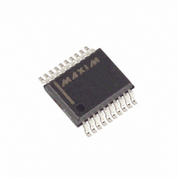
MAX1623EAP+ Maxim Integrated Products, MAX1623EAP+ Datasheet - Page 8

MAX1623EAP+
Manufacturer Part Number
MAX1623EAP+
Description
IC REG LV SYNC 3A STEPDWN 20SSOP
Manufacturer
Maxim Integrated Products
Type
Step-Down (Buck)r
Datasheet
1.MAX1623EAP.pdf
(12 pages)
Specifications of MAX1623EAP+
Internal Switch(s)
Yes
Synchronous Rectifier
Yes
Number Of Outputs
1
Voltage - Output
1.1 ~ 3.8 V
Current - Output
3A
Frequency - Switching
Up to 350kHz
Voltage - Input
4.5 ~ 5.5 V
Operating Temperature
-40°C ~ 85°C
Mounting Type
Surface Mount
Package / Case
20-SSOP
Power - Output
1.3W
Output Voltage
1.1 V to 3.8 V
Input Voltage
4.5 V to 5.5 V
Supply Current
400 uA
Switching Frequency
350 KHz
Maximum Operating Temperature
+ 85 C
Minimum Operating Temperature
- 40 C
Lead Free Status / RoHS Status
Lead free / RoHS Compliant
The internal integrator amplifier effectively eliminates any
long-term error within the time constant set by the G
the transconductance amplifier and the capacitor con-
nected to COMP. However, there remains a short-term
load-regulation error in response to load current
changes. Proper FBSEL connection selects the relative
level of current feedback to voltage feedback, which
results in an AC load-regulation error of either 1% or 2%
of the output voltage (Table 1). The 2% setting is auto-
matically selected in preset output voltage mode (FBSEL
connected to V
minimizes the size and cost of the output filter capacitor
required. For extremely tight specifications that cannot
tolerate 2% short-term errors, connect FBSEL to ground
(adjustable mode) for 1% AC load regulation (see the
Input and Output Filter Capacitors (C1, C2) section).
Synchronous rectification improves efficiency by 3% to
5% at heavy loads when compared to a conventional
Schottky rectifier. To prevent cross-conduction or “shoot-
through,” the synchronous rectifier turns on following a
short delay (dead time) after the P-channel power MOS-
FET turns off. In discontinuous (light-load) mode, the syn-
chronous rectifier switch turns off as the inductor current
approaches zero. The synchronous rectifier works under
all operating conditions, including Idle Mode.
3A, Low-Voltage, Step-Down Regulator with
Synchronous Rectification and Internal Switches
Figure 2. Standard 3.3V/3A Application Circuit
8
_______________________________________________________________________________________
4.5V TO 5.5V
NOTE: HEAVY LINES
DENOTE HIGH SWITCHING
CURRENT PATHS.
CC
INPUT
or unconnected). This gain setting
Synchronous Rectification
Setting the AC Loop Gain
10Ω
4.7µF
SHDN
FBSEL
V
FB
CC
MAX1623
m
of
COMP
PGND
TOFF
GND
REF
LX
IN
An internal transconductance amplifier fine tunes the
output DC accuracy. The transconductance amplifier is
compensated at COMP. A capacitor from COMP to
ground determines the gain-bandwidth product and the
overall loop response. This integrator effectively elimi-
nates any long-term error within the time constant set
by the G
capacitor connected to COMP.
For stability, choose COMP as follows:
where G
Table 1. Output Voltage Selection
Unconnected
FBSEL PIN
10µF
0.1µF
GND
V
IN
REF
m
4.7µH
110k
m
C
= 9.1µS.
COMP
of the transconductance amplifier and the
220µF
C1
470pF
≥
REGULATION (%)
Integrator Amplifier (COMP)
G
AC LOAD
m
×
C2
330µF
2
2
1
2
R
LOAD
4
3.3V OUTPUT
×
C
VOLTAGE (V)
OUT
Adjustable
Adjustable
OUTPUT
2.525
3.33


