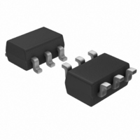
LTC1754ES6-5#TRPBF Linear Technology, LTC1754ES6-5#TRPBF Datasheet - Page 8

LTC1754ES6-5#TRPBF
Manufacturer Part Number
LTC1754ES6-5#TRPBF
Description
IC CHARGE PUMP REG SHTDN SOT23-6
Manufacturer
Linear Technology
Type
Switched Capacitor (Charge Pump)r
Datasheet
1.LTC1754ES6-5TRMPBF.pdf
(12 pages)
Specifications of LTC1754ES6-5#TRPBF
Internal Switch(s)
Yes
Synchronous Rectifier
No
Number Of Outputs
1
Voltage - Output
5V
Current - Output
50mA
Frequency - Switching
700kHz
Voltage - Input
2.7 ~ 5.5 V
Operating Temperature
-40°C ~ 85°C
Mounting Type
Surface Mount
Package / Case
SOT-23-6
Lead Free Status / RoHS Status
Lead free / RoHS Compliant
Power - Output
-
Available stocks
Company
Part Number
Manufacturer
Quantity
Price
APPLICATIO S I FOR ATIO
signal will keep V
tions. As the V
with which the LTC1754 is taken out of shutdown must
also be increased.
LTC1754-3.3/LTC1754-5
8
Figure 2. Ultralow Quiescent Current Regulated Supply
Figure 3. No-Load Supply Current vs Supply Voltage
for the Circuit Shown in Figure 2
WAVEFORM
SHDN PIN
V
OUT
LOW I
6
5
4
3
2
1
0
2.0
10 F
T
I
C
OUT
OUT
A
FLY
Q
= 25 C
MODE (2Hz TO 100Hz, 2% TO 5% DUTY CYCLE)
2.5
= 0 A
= 1 F
OUT
load current increases, the frequency
U
1
2
3
3.0
SUPPLY VOLTAGE (V)
in regulation under no-load condi-
V
LTC1754-X
GND
SHDN
OUT
LTC1754-3.3
3.5
U
LTC1754-5
V
C
C
IN
+
–
4.0
6
5
4
4.5
W
1 F
5.0
1754 F03
10 F
5.5
V
IN
U
1754 F02
Layout Considerations
Due to high switching frequency and high transient cur-
rents produced by the LTC1754, careful board layout is
necessary. A true ground plane and short connections to
all capacitors will improve performance and ensure proper
regulation under all conditions. Figure 4 shows the recom-
mended layout configuration
Thermal Management
For higher input voltages and maximum output current,
there can be substaintial power dissipation in the LTC1754.
If the junction temperature increases above approximately
150 C, the thermal shutdown circuitry will automatically
deactivate the output. To reduce the maximum junction
temperature, a good thermal connection to the PC board
is recommended. Connecting the GND pin (Pin 2) to a
ground plane and maintaining a solid ground plane under
the device on at least two layers of the PC board can reduce
the thermal resistance of the package and PC board
system to about 150 C/W.
SHDN
V
GND
OUT
V
IN
10 F
Figure 4. Recommended Layout
LTC1754-X
10 F
1 F
1754-5 F04


