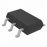
LTC1772IS6#TRPBF Linear Technology, LTC1772IS6#TRPBF Datasheet - Page 3

LTC1772IS6#TRPBF
Manufacturer Part Number
LTC1772IS6#TRPBF
Description
IC CTRLR DC/DC S-DWN SOT23-6
Manufacturer
Linear Technology
Type
Step-Down (Buck)r
Datasheet
1.LTC1772ES6TRMPBF.pdf
(12 pages)
Specifications of LTC1772IS6#TRPBF
Internal Switch(s)
No
Synchronous Rectifier
No
Number Of Outputs
1
Voltage - Output
0.8 ~ 9.8 V
Current - Output
1A
Frequency - Switching
550kHz
Voltage - Input
2.5 ~ 9.8 V
Operating Temperature
-40°C ~ 85°C
Mounting Type
Surface Mount
Package / Case
TSOT-23-6, TSOT-6
Lead Free Status / RoHS Status
Lead free / RoHS Compliant
Power - Output
-
Available stocks
Company
Part Number
Manufacturer
Quantity
Price
Note 1: Absolute Maximum Ratings are those values beyond which the life
of a device may be impaired.
Note 2: The LTC1772E is guaranteed to meet specifications from 0°C to
70°C. Specifications over the –40°C to 85°C operating temperature range
are assured by design, characterization and correlation with statistical
process controls. The LTC1772I is guaranteed to meet specified
performance from –40°C to 85°C. The LTC1772H is guaranteed to meet
specified performance from –40°C to 140°C.
Note 3: T
dissipation P
ELECTRICAL CHARACTERISTICS
TYPICAL PERFOR A CE CHARACTERISTICS
T
J
825
820
815
810
805
800
795
790
785
780
775
= T
–55 –35 –15 5
Reference Voltage
vs Temperature
J
A
V
is calculated from the ambient temperature T
+ (P
IN
D
= 4.2V
according to the following formula:
D
130
120
110
100
• θ
90
80
70
60
50
20
JA
Maximum (V
vs Duty Cycle
TEMPERATURE (°C)
°C/W)
25 45 65 85 105 125 145
30
40
DUTY CYCLE (%)
50
IN
W
– SENSE
60
1772 G01
70
U
–
) Voltage
80
V
T
IN
A
= 25°C
= 4.2V
90
1772 G04
A
–10
and power
10
–2
–4
–6
–8
8
6
4
2
0
100
–55 –35 –15 5
Normalized Frequency
vs Temperature
V
IN
= 4.2V
TEMPERATURE (°C)
25 45 65 85 105 125 145
Operation at high junction temperatures degrades operating lifetimes.
Operating lifetimes at junction temperatures greater than 125°C is derated
to 1000 hours.
Note 4: Dynamic supply current is higher due to the gate charge being
delivered at the switching frequency.
Note 5: The LTC1772 is tested in a feedback loop that servos V
output of the error amplifier.
Note 6: Peak current sense voltage is reduced dependent on duty cycle to
a percentage of value as given in Figure 2.
1772 G02
550
510
470
430
390
350
310
270
230
190
150
–55 –35 –15 5
Shutdown Threshold
vs Temperature
V
IN
= 4.2V
2.14
2.10
2.06
2.02
1.98
1.94
1.90
1.86
1.82
1.78
1.74
–55 –35 –15 5
Undervoltage Lockout Trip
Voltage vs Temperature
TEMPERATURE (°C)
V
IN
25 45 65 85 105 125 145
FALLING
TEMPERATURE (°C)
25 45 65 85 105 125 145
LTC1772
1772 G05
FB
to the
1772 G03
1772fb
3


