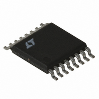
LT1940EFE#TRPBF Linear Technology, LT1940EFE#TRPBF Datasheet - Page 9

LT1940EFE#TRPBF
Manufacturer Part Number
LT1940EFE#TRPBF
Description
IC REG SW DUAL 1.4A STDN 16TSSOP
Manufacturer
Linear Technology
Type
Step-Down (Buck)r
Datasheet
1.LT1940EFEPBF.pdf
(20 pages)
Specifications of LT1940EFE#TRPBF
Internal Switch(s)
Yes
Synchronous Rectifier
No
Number Of Outputs
2
Voltage - Output
1.25 ~ 22 V
Current - Output
1.4A
Frequency - Switching
1.1MHz
Voltage - Input
3.6 ~ 25 V
Operating Temperature
-40°C ~ 85°C
Mounting Type
Surface Mount
Package / Case
16-TSSOP Exposed Pad, 16-eTSSOP, 16-HTSSOP
Lead Free Status / RoHS Status
Lead free / RoHS Compliant
Power - Output
-
Available stocks
Company
Part Number
Manufacturer
Quantity
Price
Table 1. Inductors.
Part Number
Sumida
CR43-1R4
CR43-2R2
CR43-3R3
CR43-4R7
CDRH3D16-1R5
CDRH3D16-2R2
CDRH3D16-3R3
CDRH4D28-3R3
CDRH4D28-4R7
CDRH5D28-5R3
CDRH5D18-4R1
Coilcraft
DO1606T-152
DO1606T-222
DO1606T-332
DO1606T-472
DO1608C-152
DO1608C-222
DO1608C-332
DO1608C-472
1812PS-222M
1008PS-182M
Murata
LQH32CN1R0M11L
LQH32CN2R2M11L
LQH43CN1R5M01L
LQH43CN2R2M01L
LQH43CN3R3M01L
APPLICATIO S I FOR ATIO
Input Capacitor Selection
Bypass the input of the LT1940 circuit with a 4.7 F or
higher ceramic capacitor of X7R or X5R type. A lower value
or a less expensive Y5V type can be used if there is
additional bypassing provided by bulk electrolytic or
tantalum capacitors. The following paragraphs describe
the input capacitor considerations in more detail.
Step-down regulators draw current from the input supply
in pulses with very fast rise and fall times. The input
capacitor is required to reduce the resulting voltage ripple
Value
U
( H)
1.4
2.2
3.3
4.7
1.5
2.2
3.3
3.3
4.7
5.3
4.1
1.5
2.2
3.3
4.7
1.5
2.2
3.3
4.7
2.2
1.8
1.0
2.2
1.5
2.2
3.3
U
(A) DC
2.52
1.75
1.44
1.15
1.55
1.20
1.10
1.57
1.32
1.95
2.10
1.70
1.30
1.10
2.60
2.30
2.00
1.50
1.00
0.79
1.00
0.90
0.80
I
1.9
1.7
2.1
SAT
W
0.056
0.071
0.086
0.109
0.040
0.050
0.063
0.049
0.072
0.028
0.042
0.060
0.070
0.100
0.120
0.050
0.070
0.080
0.090
0.070
0.090
0.078
0.126
0.090
0.110
0.130
DCR
( )
U
Height
(mm)
3.81
2.74
3.5
3.5
3.5
3.5
1.8
1.8
1.8
3.0
3.0
3.0
2.0
2.0
2.0
2.0
2.0
2.9
2.9
2.9
2.9
2.2
2.2
2.8
2.8
2.8
at the LT1940 and to force this very high frequency
switching current into a tight local loop, minimizing EMI.
The input capacitor must have low impedance at the
switching frequency to do this effectively, and it must have
an adequate ripple current rating. With two switchers
operating at the same frequency but with different phases
and duty cycles, calculating the input capacitor RMS
current is not simple. However, a conservative value is the
RMS input current for the channel that is delivering most
power (V
and is largest when V
second, lower power channel draws input current, the
input capacitor’s RMS current actually decreases as the
out-of-phase current cancels the current drawn by the
higher power channel. Considering that the maximum
load current from a single channel is ~1.4A, RMS ripple
current will always be less than 0.7A.
The high frequency of the LT1940 reduces the energy
storage requirements of the input capacitor, so that the
capacitance required is less than 10 F. The combination
of small size and low impedance (low equivalent series
resistance or ESR) of ceramic capacitors make them the
preferred choice. The low ESR results in very low voltage
ripple and the capacitors can handle plenty of ripple
current. They are also comparatively robust and can be
used in this application at their rated voltage. X5R and X7R
types are stable over temperature and applied voltage, and
give dependable service. Other types (Y5V and Z5U) have
very large temperature and voltage coefficients of capaci-
tance, so they may have only a small fraction of their
nominal capacitance in your application. While they will
still handle the RMS ripple current, the input voltage ripple
may become fairly large, and the ripple current may end up
flowing from your input supply or from other bypass
capacitors in your system, as opposed to being fully
sourced from the local input capacitor.
An alternative to a high value ceramic capacitor is a lower
value along with a larger electrolytic capacitor, for ex-
ample a 1 F ceramic capacitor in parallel with a low ESR
tantalum capacitor. For the electrolytic capacitor, a value
larger than 10 F will be required to meet the ESR and
ripple current requirements. Because the input capacitor
C
INRMS
OUT
= I
OUT
• I
OUT
[V
). This is given by:
OUT
IN
= 2V
• (V
LT1940/LT1940L
OUT
IN
– V
(50% duty cycle). As the
OUT
)]/V
IN
< I
OUT
/2
1940fa
9


