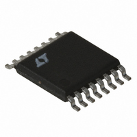
LT1956IFE#TR Linear Technology, LT1956IFE#TR Datasheet - Page 13

LT1956IFE#TR
Manufacturer Part Number
LT1956IFE#TR
Description
IC REG SW 1.5A HV STPDWN 16TSSOP
Manufacturer
Linear Technology
Type
Step-Down (Buck)r
Datasheet
1.LT1956EGNPBF.pdf
(28 pages)
Specifications of LT1956IFE#TR
Internal Switch(s)
Yes
Synchronous Rectifier
No
Number Of Outputs
1
Voltage - Output
1.2 ~ 45 V
Current - Output
1.5A
Frequency - Switching
500kHz
Voltage - Input
5.5 ~ 60 V
Operating Temperature
-40°C ~ 125°C
Mounting Type
Surface Mount
Package / Case
16-TSSOP Exposed Pad, 16-eTSSOP, 16-HTSSOP
Lead Free Status / RoHS Status
Contains lead / RoHS non-compliant
Power - Output
-
Available stocks
Company
Part Number
Manufacturer
Quantity
Price
APPLICATIO S I FOR ATIO
where:
f = switching frequency
t
V
V
I • R = inductor I • R voltage drop
If this condition is not observed, the current will not be
limited at I
higher value. Using the nominal LT1956 clock frequency
of 500KHz, a V
maximum t
116ns, an unacceptably short time.
The solution to this dilemma is to slow down the oscillator
when the FB pin voltage is abnormally low thereby indicat-
ing some sort of short-circuit condition. Oscillator fre-
quency is unaffected until FB voltage drops to about 2/3 of
its normal value. Below this point the oscillator frequency
decreases roughly linearly down to a limit of about 100kHz.
This lower oscillator frequency during short-circuit condi-
tions can then maintain control with the effective mini-
mum on time. Even with frequency foldback, however, the
LT1956 will not survive a permanent output short at the
absolute maximum voltage rating of V
defined solely by internal semiconductor junction break-
down effects.
For the maximum input voltage allowed during an output
short to ground, the previous equation defining minimum
on-time can be used. Assuming V
0.63V at 1A (short-circuit current is folded back to typical
switch current limit • 0.5), I (inductor) • DCR = 1A • 0.128
= 0.128V (L = CDRH6D28-22), typical f = 100kHz (folded
back) and typical minimum on-time = 300ns, the maxi-
mum allowable input voltage during an output short to
ground is typically:
Increasing the DCR of the inductor will increase the maxi-
mum V
also drop overall efficiency during normal operation.
Every time the converter wakes up from shutdown or
undervoltage lockout to begin switching, the output
ON
F
IN
V
V
= diode forward voltage
= switch minimum on time
= input voltage
IN
IN(MAX)
= (0.63V + 0.128V)/(100kHz • 300ns)
IN
allowed during an output short to ground but will
PK
ON
= 25V
, but will cycle-by-cycle ratchet up to some
to maintain control would be approximately
IN
of 12V and a (V
U
U
F
+ I • R) of say 0.7V, the
W
F
(D1 catch diode) =
IN
= 60V; this is
U
capacitor may potentially be starting from 0V. This re-
quires that the part obey the overall duty cycle demanded
by the loop, related to V
rises to its target value. It is recommended that for [V
(V
to control the output capacitor charge rate during start-up
or during recovery from an output short circuit, thereby
adding additional control over peak inductor current. See
Buck Converter with Adjustable Soft-Start later in this
data sheet.
OUTPUT CAPACITOR
The LT1956 will operate with either ceramic or tantalum
output capacitors. The output capacitor is normally cho-
sen by its effective series resistance (ESR), because this
is what determines output ripple voltage. The ESR range
for typical LT1956 applications using a tantalum output
capacitor is 0.05 to 0.2 . A typical output capacitor is an
AVX type TPS, 100 F at 10V, with a guaranteed ESR less
than 0.1 . This is a “D” size surface mount solid tantalum
capacitor. TPS capacitors are specially constructed and
tested for low ESR, so they give the lowest ESR for a given
volume. The value in microfarads is not particularly criti-
cal, and values from 22 F to greater than 500 F work well,
but you cannot cheat mother nature on ESR. If you find a
tiny 22 F solid tantalum capacitor, it will have high ESR,
and output ripple voltage will be terrible. Table 3 shows
some typical solid tantalum surface mount capacitors.
Table 3. Surface Mount Solid Tantalum Capacitor ESR
and Ripple Current
E CASE SIZE
AVX TPS, Sprague 593D
D CASE SIZE
AVX TPS, Sprague 593D
C CASE SIZE
AVX TPS
Unlike the input capacitor, RMS ripple current in the
output capacitor is normally low enough that ripple cur-
rent rating is not an issue. The current waveform is
triangular with a typical value of 125mA
to calculate this is:
OUT
+ V
F
)] ratios > 4, a soft-start circuit should be used
IN
ESR (MAX,
and V
0.1 to 0.3
0.1 to 0.3
0.2 (typ)
LT1956/LT1956-5
OUT
, as the output voltage
)
RIPPLE CURRENT (A)
RMS
. The formula
0.7 to 1.1
0.7 to 1.1
0.5 (typ)
13
1956f
IN
/


