LM2618ATL National Semiconductor, LM2618ATL Datasheet
LM2618ATL
Specifications of LM2618ATL
Available stocks


Related parts for LM2618ATL


LM2618ATL Summary of contents
Page 1
... Only three small external surface-mount components, an inductor and two ceramic capacitors are required. Typical Application Circuit © 2002 National Semiconductor Corporation Key Specifications n Operates from a single LiION cell (2.8V to 5.5V) n Internal synchronous rectification provides high efficiency in both PWM and PFM n Pin programmable output voltage (1 ...
Page 2
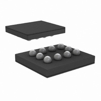
... Package Type 10-Pin micro SMD LM2618ATL LM2618BTL 10-bump Wafer Level Chip Scale (micro SMD) LM2618ATLX LM2618BTLX (*) XY - denotes the date code marking (2 digit) in production (*) TT - refers to die run/lot traceability for production (*) I - pin one indication (*) S - Product line designator Note that Package Marking may change over the course of production www ...
Page 3
Pin Description Pin Number (*) Pin Name A1 FB Feedback Analog Input. Connect to the output at the output filter capacitor (Figure 1) B1 VID1 Output Voltage Control Inputs. Set the output voltage using these digital inputs (see Table 1). ...
Page 4
... Minimum ESD Rating −0.2V to +6V Human body model 100pF 1.5 kΩ −0.2V to +0.2V Thermal Resistance (θ LM2618ATL & LM2618BTL (Note 3) −0.2V to +6V (GND −0.2V) to (VDD +0.2V) −45˚C to +150˚ 25˚C, and those in bold face type apply over the full Operating Tem- ...
Page 5
... Note 8: SYNC driven with an external clock switching between VDD and GND. When an external clock is present at SYNC, the IC is forced to PWM mode at the external clock frequency. The LM2618 synchronizes to the rising edge of the external clock. (Continued 25˚C, and those in bold face type apply over the full Operating Tem Conditions LM2618ATL, PWM Mode (SYNC = VIN) LM2618BTL, PWM Mode (SYNC = VIN) 5 Min Typ Max ...
Page 6
... Quiescent Supply Current vs Temperature (V =1.8V) OUT Shutdown Quiescent Current vs Temperature Output Voltage vs Temperature (V = 1.8V, PFM Mode) OUT www.national.com LM2618ATL, Circuit of Figure 1, V Quiescent Supply Current vs Supply Voltage 20036406 Output Voltage vs Temperature ( V 20036421 Output Voltage vs Supply Voltage (V OUT 20036407 6 = 3.6V 25˚ ...
Page 7
... Output Voltage vs Supply Voltage (V = 1.8V, PFM Mode) OUT Output Voltage vs Output Current (V = 1.8V, PFM Mode) OUT Efficiency vs Output Current (V = 1.8V, PFM Mode) OUT LM2618ATL, Circuit of Figure 1, V Output Voltage vs Output Current (V OUT 20036419 Efficiency vs Output Current (V OUT 20036420 Switching Frequency vs Temperature 20036424 7 = 3.6V 25˚ ...
Page 8
... Typical Operating Characteristics unless otherwise noted. (Continued) PWM to PFM Response Load Transient Response (PWM Mode) Line Transient Response (PWM Mode) www.national.com LM2618ATL, Circuit of Figure 1, V Shutdown Response (PWM Mode) 20036413 Load Transient Response (PFM Mode) 20036412 20036416 8 = 3.6V 25˚ µ 20036414 ...
Page 9
Device Information The LM2618 is a simple, step-down DC-DC converter opti- mized for powering low-voltage CPUs or DSPs in cell phones and other miniature battery powered devices. It pro- vides pin-selectable output voltages of 1.80V, 1.83V, 1.87V or 1.92V from ...
Page 10
Circuit Operation (Continued) PWM Operation The LM2618 can be set to current-mode PWM operation by connecting the SYNC/MODE pin to VDD. While in PWM (Pulse Width Modulation) mode, the output voltage is regu- lated by switching at a constant frequency ...
Page 11
PFM Operation Connecting the SYNC/MODE pin to SGND sets the LM2618 to hysteretic PFM operation. While in PFM (Pulse Frequency Modulation) mode, the output voltage is regulated by switch- ing with a discrete energy per cycle and then modulating the ...
Page 12
Current Limiting A current limit feature allows the LM2618 to protect itself and external components during overload conditions. Current limiting is implemented using an independent internal com- parator. In PWM mode, cycle-by-cycle current limiting is normally used excessive ...
Page 13
... Micro SMD Package Assembly and Use Use of the micro SMD package requires specialized board layout, precision mounting and careful reflow techniques, as detailed in National Semiconductor Application Note AN-1112. Refer to the section Surface Mount Technology (SMT) Assembly Considerations. For best results in assem- bly, alignment ordinals on the PC board should be used to facilitate placement of the device ...
Page 14
Application Information 3. Arrange the components so that the switching current loops curl in the same direction. During the first part of each cycle, current flows from the input filter capacitor, through the LM2618 and inductor to the output filter ...
Page 15
... NATIONAL’S PRODUCTS ARE NOT AUTHORIZED FOR USE AS CRITICAL COMPONENTS IN LIFE SUPPORT DEVICES OR SYSTEMS WITHOUT THE EXPRESS WRITTEN APPROVAL OF THE PRESIDENT AND GENERAL COUNSEL OF NATIONAL SEMICONDUCTOR CORPORATION. As used herein: 1. Life support devices or systems are devices or systems which, (a) are intended for surgical implant ...